----------------------------------
LCD-Ill
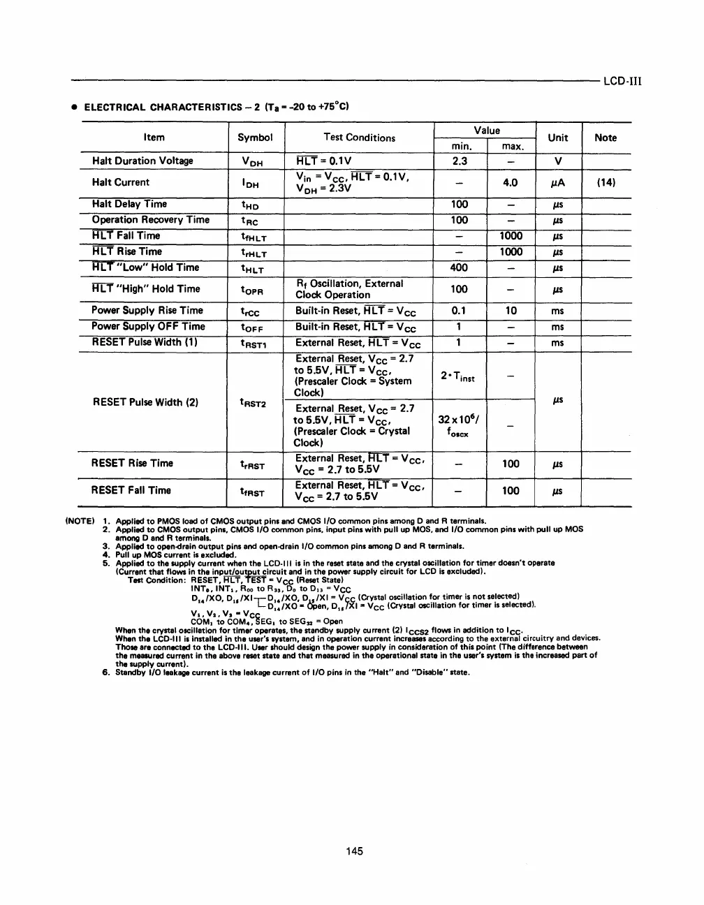
• ELECTRICAL CHARACTERISTICS - 2 (Ta =
-20
to
+75°C)
Item
Symbol
Test
Conditions
Value
Unit
min.
max.
Halt
Duration
Voltage
V
OH
HLT
=
O.1V
2.3
-
V
Halt
Current
IOH
Yin
=Vee,HLT=O.1V,
V
OH
=
2.3V
-
4.0
IlA
Halt
Delay
Time
tHo
100
-
Ils
Operation
Recovery
Time
tRe
100
-
IJ.S
HLT
Fall
Time
tfHLT
-
1000
IlS
HL
T
Rise
Time
trHLT
-
1000
IJ.S
HLT"Low"
Hold
Time
tHLT
400
-
IlS
H L T
"High"
Hold
Time
tO
PR
R
f
Oscillation,
External
100
-
IlS
Clock
Operation
Power
Supply
Rise
Time
tree
Built-in
Reset,
HLT
=
Vee
0.1
10
ms
Power
Supply
OFF
Time
tOFF
Built-in
Reset,
H L T =
Vee
1
-
ms
RESET
Pulse
Width
(1)
tRST1
External
Reset,
H L T =
Vee
1
-
ms
External
Reset,
Vee
-
2.7
to
5.5V,
HLT
=
Vee,
(Prescaler
Clock
=
System
2'
T
inst
-
Clock)
Ils
RESET
Pulse
Width
(2)
tRST2
External
Reset,
Vee
=
2.7
to
5.5V,
HLT
=
Vee,
32
x
10
6
/
-
(Prescaler
Clock
=
Crystal
f
o,cx
Clock)
RESET
Rise
Time
trRST
External
Reset,
RLT =
Vee,
-
100
IlS
Vee
=
2.7
to
5.5V
RESET
Fall
Time
tfRST
External
Reset,
H L T =
Vee,
-
100
IJ.S
Vee
=
2.7
to
5.5V
INOTEI
1. Applied
to
PMOS
load
of
CMOS
output pins and
CMOS
I/O
common pins among 0 and R terminals.
2. Applied
to
CMOS
output pins,
CMOS
I/O common pins, input pins with pull
up
MOS,
and
I/O
common pins with pull
up
MOS
among 0 and R terminals.
3.
Applied
to
open<irain output pins and open<irain
I/O
common pins among 0 and R terminals.
4.
Pull
up
MOS
currant
is
axcluded.
5. Applied
to
the supply current when the
LCD-III
is
in
the reset state and the crystal oscillation for timer doesn't operate
ICurrent that flows
in
the input/ouljut circuit and
in
the power supply circuit for
LCD
is
excluded).
Test Condition:
RESET,
HLT,
EST
=
Vee
IReset State I
INTo, INTI,
Roo
to R
u
,
Do
to 0
13
=
Vee
D
I4
/XO, D
u
/XI,-D
I4
/XO,
D.1../XI
=
Vee
(Crystal oscillation
~or
~imer
is
~ot
se!ectedl
LOu/XO
- upen,
Ou/XI
..
VCC
ICrystal
OSCillation
for timer IS selected).
~bM~2
toVC;M~~~EGI
to
SEG
n
= Open
Note
(14)
When
tha crystal oscillation for timer operates, the standby supply current
121
IcCS2
flows
in
addition to
Icc.
When
the
LCD-III
is
installed
in
the user's system, and
in
operation current increases according to the external circuitry and devices.
Those are connected
to
the
LCD-III.
User
should design the power supply
in
consideration of this point IThe difference between
the measured current
in
the above reset stata and that measured
in
the operatio.nal state
in
tha user's system
is
the increased part of
the supply current!.
6.
Standby
I/O
leakage
current
is
the leakage current of I/O pins
in
the "Halt" and "Disable" state.
145
 Loading...

