LCD-II1--------------------------------
• Liquid
Cryltil
Display Mode Setting Regilters
For
selection
of
the liquid crystal display mode, data I/O registers
of
R4,
R5
and R6 are used.
Table 5 Function
of
Liquid Crystal Display Mode Setting Registers
R41
R40
Function
0 0
Static
Selection
of
liquid crystal
0
1
1/2
duty
display
duty
factor
(R
40
, R
41
)
1
0
1/3
duty
1 1
1/4
duty
Designation of with
or
without
R42
Function
liquid crystal segment
output
0
To be extended (Outputs display data from Channel R 1 )
extension
(R
42
)
1
Not
to
be extended (Channel
R1.
becomes an ordinary 4-bit data I/O.)
R60
Function
liquid
crystal display blanking
0
Outputs
RAM
data for liquid crystal display
as
segment signals.
signal
(R60)
1
Segment signals become non-selection status (blanking) regardless
of
RAM
designation for liquid
crystal display
(R
so
, Rs.)
RAM
data for liquid crystal display.
(NOTE) LiQuid crystal display mode
at
resetting
Since all bits
of
registers R4, R5 and R6 are set
to
"1"
by
the
reset function, display mode after resetting becomes as shown below:
Liquid crystal display
duty
factor:
1/4
duty
(R
40
-
"1",
R
41
'"
"1")
~,!d
crystal segment
output
extension: Not extended
(R42
=
"1")
;",nation
of
liquid crystal display blanking: Display blanking
(R,o
-
"1")
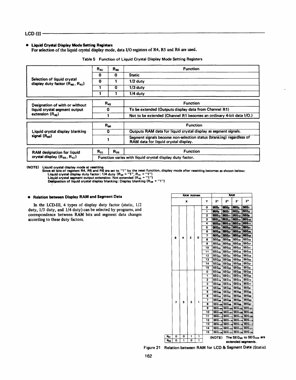
• Relation between Display
RAM
and Segment Data
In the LCD-III, 4 types
of
display duty factor (static, 1/2
duty, 1/3 duty, and
1/4
duty) can be selected by programs, and
correspondence between
RAM
bits and segment data changes
according
to
these duty factors.
(NOTE) The SEG
..
to
SEGI2I are
extended
segments.
Figure
21
Relation between
RAM
for
LCD
& Segment Data (Static)
162
 Loading...

