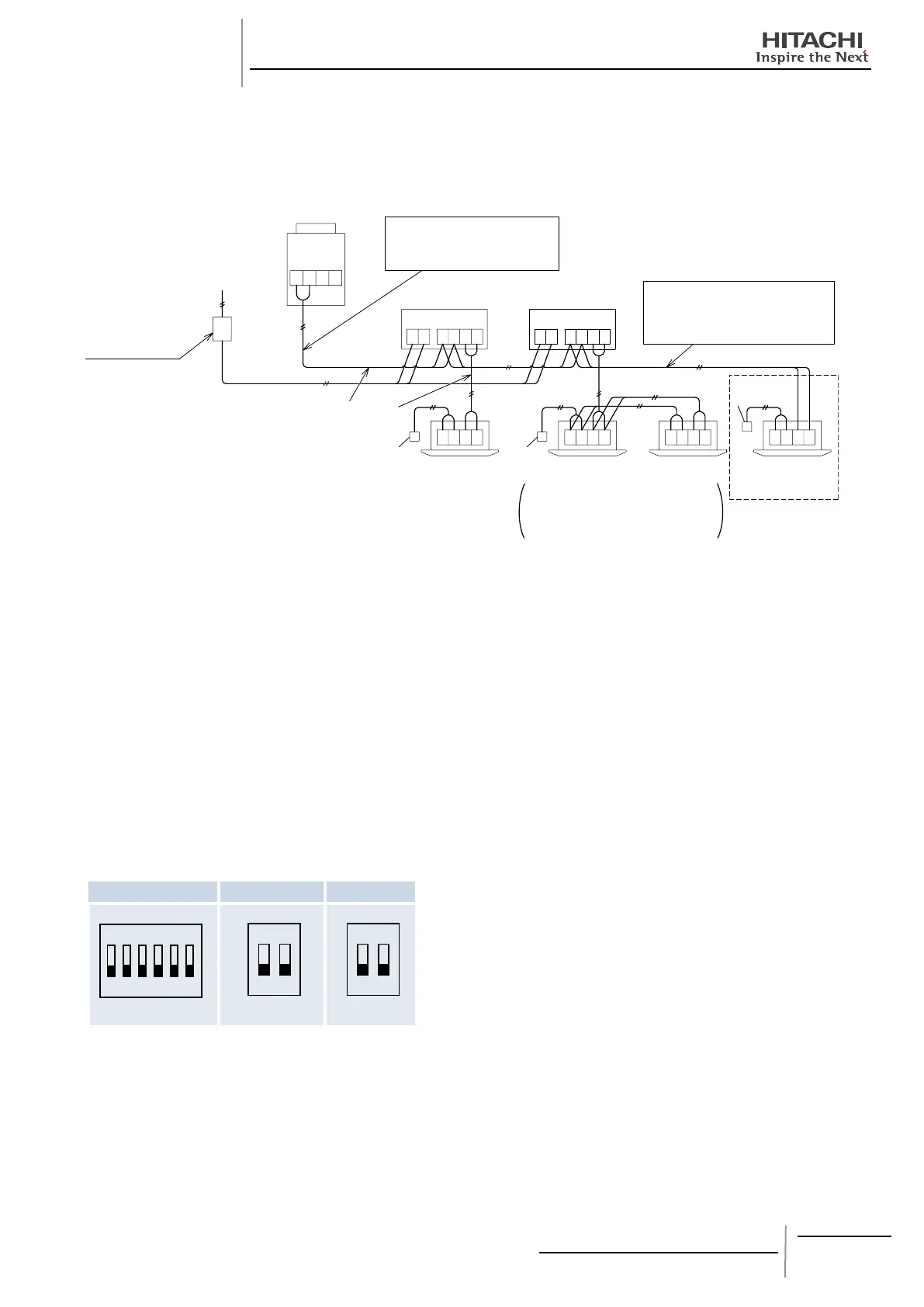
¡ Example of Electrical Wiring
S
NOTE:
Do not apply excessive voltage to the operating line (DC5V (non-pole)) between outdoor unit and CH unit, between CH unit
and indoor unit, between CH units.
Use 2-Core cable for the operating line. (Do not use 3-Core cable or over.)
Connect the operating line for the outdoor unit to the terminal “1” and “2” of TB2 on the CH unit.
Connect the operating line for the indoor unit exclusively for cooling operation to the terminal “1” and “2” of TB2 on the CH unit.
For the CH unit in the same refrigerant cycle, electrical power source can be supplied by one switch.
Do not connect the power supply line (220V~240V) to the terminal board for operating line.
Connect the earth wire for the outdoor/indoor units and CH unit. The ground wiring work under the condition of 100
W (max.)
ground resistance should be performed by the qualied electrician.
¡ Setting of Dip Switches
DSW1 DSW101 SW301
NOTE:
The “ n” mark indicates position of dip switches. Figures
show setting before shipment.
CAUTION:
The control of the temperature is only available through the
room’s thermostat or Aquastat. The Remote Control Switch
of the indoor unit cannot be touch, if it is done the unit will
be outside of warranty.
Before setting dip switches, rstly turn OFF power source
and set the position of the dip switches. If the switches are
set without turning OFF the power source, the switches can
not function.