3 Screw the rear support screw to the arm and the stand will be completely mounted.
Rear support screw
4 Finally, connect the power supply and LAN cable to the CSNET Manager.
5 Press down the power switch.
6 CSNET Manager program starts automatically.
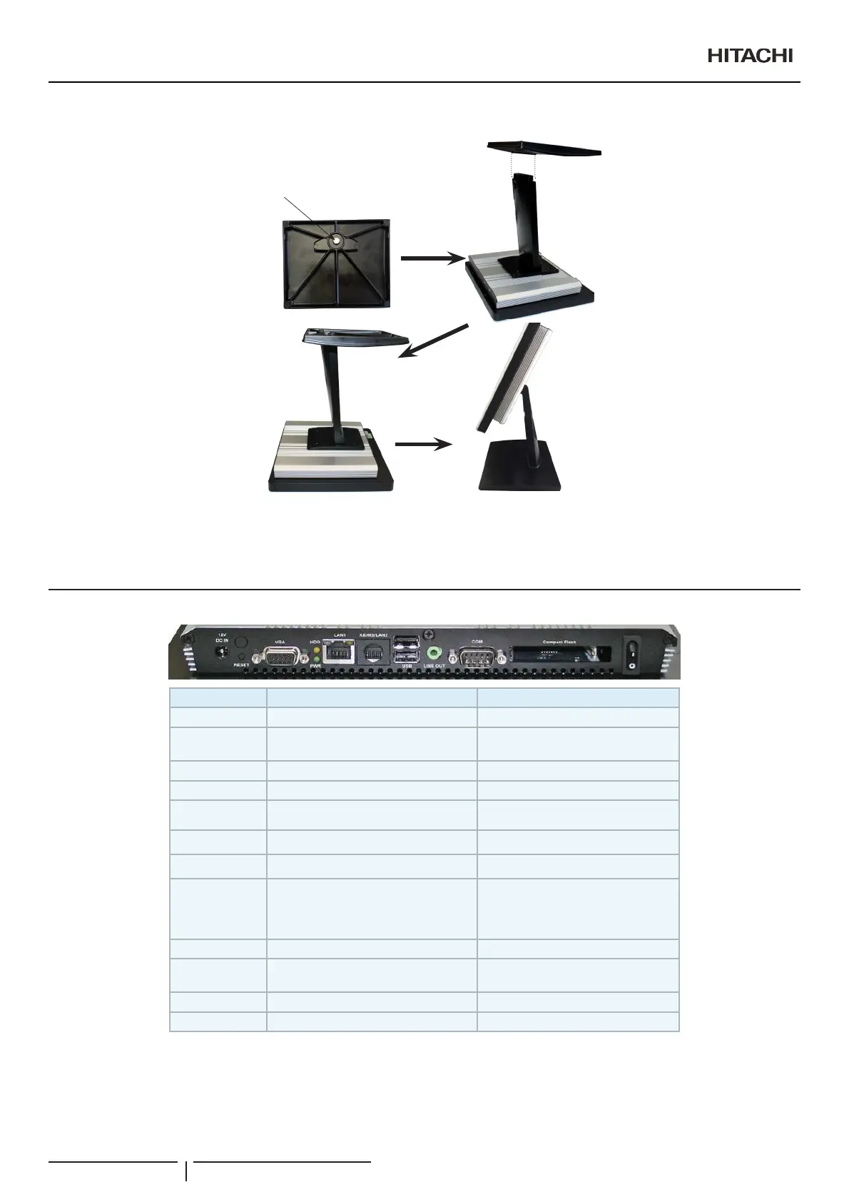
2.3 CONNECTORS DESCRIPTION
Label Function Note
POWER Power on button
Compact Flash/
COM2
CF Type I/II Socket with Ejector Optional for 2nd COM port
COM1 Serial port 1 connector DB-9 male connector
LINE OUT Line-out audio jack
USB 2 x USB 2.0 connector Dock USB
LAN1 5-(WKHUQHWFRQQHFWRU
HDD HDD indicator
KB/MS (LAN2)
LPC-1705/1707 -- PS/2 connector
LPC-17A4 -- LAN2
For CSNET Manager XT it is a LAN2
5-(WKHUQHWFRQQHFWRU$OZD\V
connect Ethernet to LAN1. LAN2 is
disabled by software
PWR System power indicator
9*$+'0,
CRT connector/HDMI
connector
RESET Reset button
DC-IN DC Power-in connector
Installation
PMML0409A rev.1 - 10/201622
 Loading...