)-E99
I
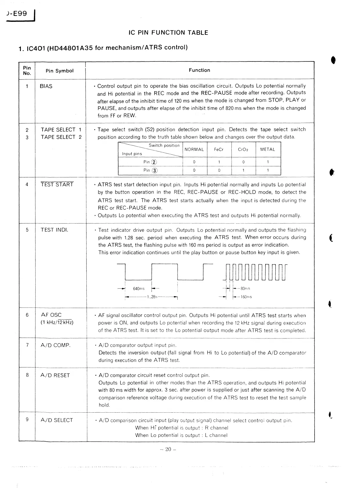
IC PIN FUNCTION TABLE
1.
IC401
(HD44801
A35
for
mechanism/
ATRS control)
Pin
I
No.
Pin
Symbol
Function •
1
BIAS
• Control output pin to operate the
bias
oscillation circuit. Outputs
Lo
potential normally
and Hi potential
in
the
REC
mode
and
the REC-PAUSE mode after recording.
Outputs
after elapse
of
the
inhibit
time
of
120
ms
when the mode is changed from STOP, PLAY
or
PAUSE,
and
outputs after elapse of the inhibit time
of
820
ms
when the mode is changed
from
FF
or
REW.
2
TAPE SELECT
1
• Tape select switch (S2) position detection input pin.
Detects the tape
select switch
3
TAPE SELECT 2
position according
to the truth table shown below and changes over the
output
data.
I
~n
NORMAL
FeCr
Cr02
METAL
I
s
Pin(V
0 1 0
1
Pin@
I
0
0
1 1
4
TEST START • ATRS test start detection input pin. Inputs Hi potential normally
and
inputs
Lo
potential
by
the button operation
in
the
REC,
REC-PAUSE
or
REC-HOLD mode, to detect the
ATRS test start. The
ATRS
test starts actually when the input is detected during the
REC
or REC-PAUSE mode.
• Outputs
Lo
potential when executing the ATRS
test
and
outputs Hi potential normally.
5 TEST INDI.
·
Test indicator drive
output
pin. Outputs Lo potential normally
and
outputs
the flashing
pulse with
1.28
sec. period when executing the
ATRS
test. When error occurs during
(
the ATRS test, the flashing pulse with
160
ms period is
output
as
error indication.
This error indication continues
until the play button
or
pause button
key
input is given.
l I I
I
J1IU1illlJ1JUUl
!
I
I
-H
~-Borns
I
--1
640ms
r-
1
i
1.28s
I
--i
f---160nis
••
6
AFOSC
• AF signal oscillator control
output
pin.
Outputs Hi potential until ATRS test
starts
when
(1
kHz/12 kHz)
I
power
is
ON,
and
outputs
Lo
potential
when
recording the
12
kHz
signal during execution
I
of
the ATRS test. It is set to the
Lo
potential
output
mode after A TRS test is completed.
"-
7
A/D
COMP.
i
·
A/D
comparator output input pin.
I
Detects the inversion
output
(fall signal from
Hi to
Lo
potential)
of
the
A/D
comparator
during execution
of
the
ATRS
test.
---
8
A/D
RESET
•
A/D
comparator circuit reset control output pin.
Outputs
Lo
potential
in
other
modes
than the ATRS operation,
and
outputs
Hi potential
with
80
ms
width
for
approx. 3
sec.
after power is supplied
or
just
after scanning the
A/D
comparison reference voltage during execution
of
the ATRS test to reset the
test
sample
hold.
9
A/D
SELECT
I
·
A/D
comparison circuit input (play output signal) channel select control
output
pin.
When
Hi
potential
is
output : R channel
When
Lo
potential
is
output : L channel
- 20 -
 Loading...