Pin
Pin
Symbol
Function
No.
•
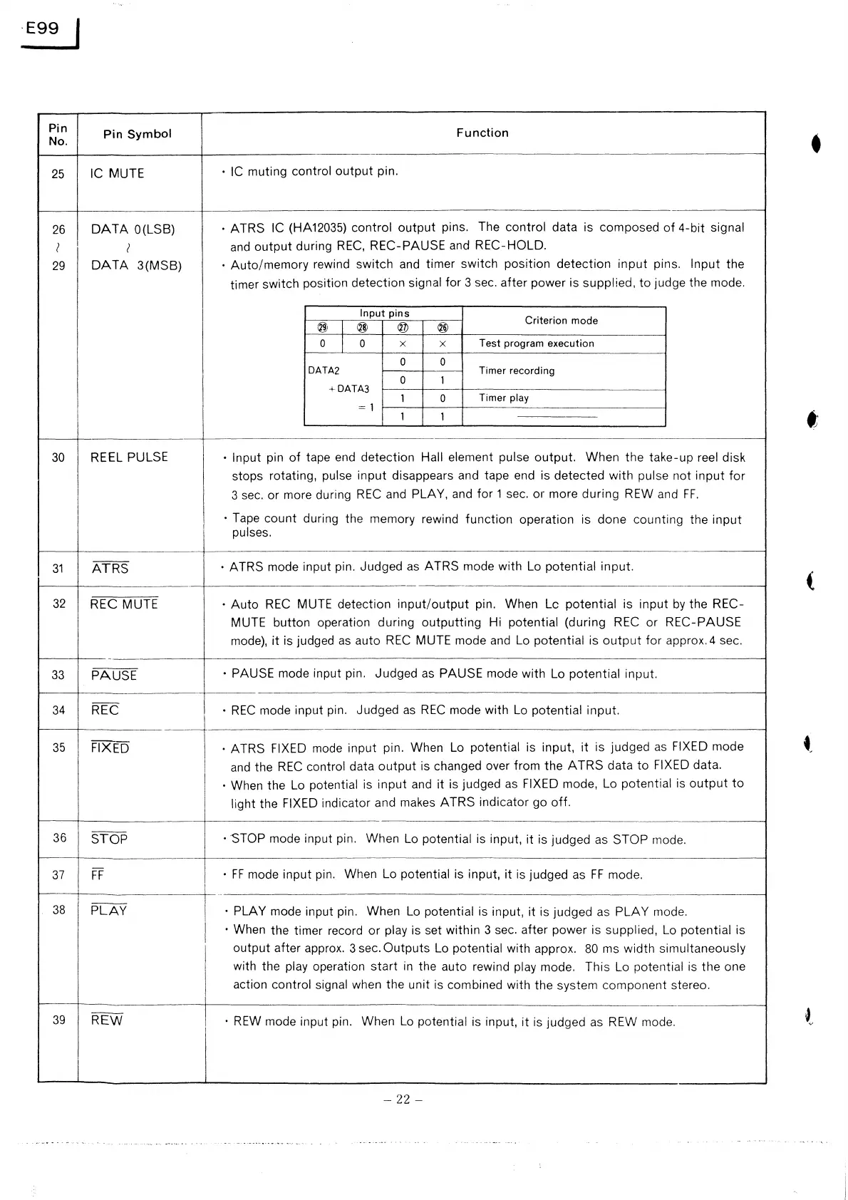
25
IC MUTE
• IC muting control
output
pin.
26
DATA
O(LSB)
• ATRS IC
(HA12035) control
output
pins.
The control data is
composed
of
4-bit signal
I
I
and
output
during
REC,
REC-PAUSE and REC-HOLD.
29
DATA
3(MSB)
•
Auto/memory
rewind switch and timer switch position
detection
input
pins. Input the
timer switch position detection signal for 3 sec. after power is supplied,
to
judge the mode.
Input
pins
Criterion
mode
®
I
® ®
®
0
I
0
x x
Test
program
execution
0 0
DATA2
Timer recording
0
1
+ DATA3
1 0
Timer play
= 1
1 1
••
30
REEL PULSE
• Input
pin
of
tape end detection Hall element pulse
output.
When the take-up reel disk
stops rotating, pulse input disappears and tape end is detected
with
pulse
not
input
for
3 sec. or more during
REC
and PLAY, and
for
1 sec. or more
during
REW and
FF.
I
• Tape count
during the memory rewind function operation is done
counting the
input
I
pulses.
---·--------.
31
ATRS
· ATRS mode input pin. Judged as ATRS mode with Lo potential input.
(
32
REC MUTE
•
Auto
REC
MUTE detection
input/output
pin. When Le potential is
input
by
the REC-
MUTE button operation during
outputting
Hi potential (during REC or
REC-PAUSE
mode),
it
is judged
as
auto
REC
MUTE mode and Lo potential is
output
for
approx. 4 sec.
33
PAUSE
· PAUSE mode input pin.
Judged
as
PAUSE mode with Lo potential input.
~---
34
REC
•
REC
mode input pin. Judged
as
REC
mode with Lo potential input.
I
-l
--
--
35
FIXED
· ATRS FIXED
mode input pin. When Lo potential is input,
it
is judged
as
FIXED mode
and
the
REC
control data
output
is changed over from the A TRS data
to
FIXED data.
I
· When the Lo potential is
input
and
it
is judged
as
FIXED mode, Lo potential is
output
to
I
light the FIXED indicator and makes
ATRS
indicator go
off.
-----------~----
36
STOP
·~TOP
mode input pin.
When Lo potential is input,
it
is judged as STOP mode.
-----
-
37
FF
·
FF
mode input pin.
When Lo potential is input,
it
is judged as
FF
mode.
I
38
PLAY
• PLAY mode input pin. When Lo potential is input,
it
is judged as
PLAY
mode.
• When the timer record
or
play is set within 3 sec. after power is supplied,
Lo
potential is
I
output
after approx. 3 sec.
Outputs
Lo potential with approx.
80
ms width simultaneously
I
with the play operation
start
in
the auto rewind play mode.
This Lo
potential is
the
one
action
control signal when the unit is combined with the system component stereo.
I
-
----------~----
39
REW
·
REW
mode input pin.
When
Lo
potential is input,
it
is judged as REW mode.
-
22
-
 Loading...