0
(
t
D-E99
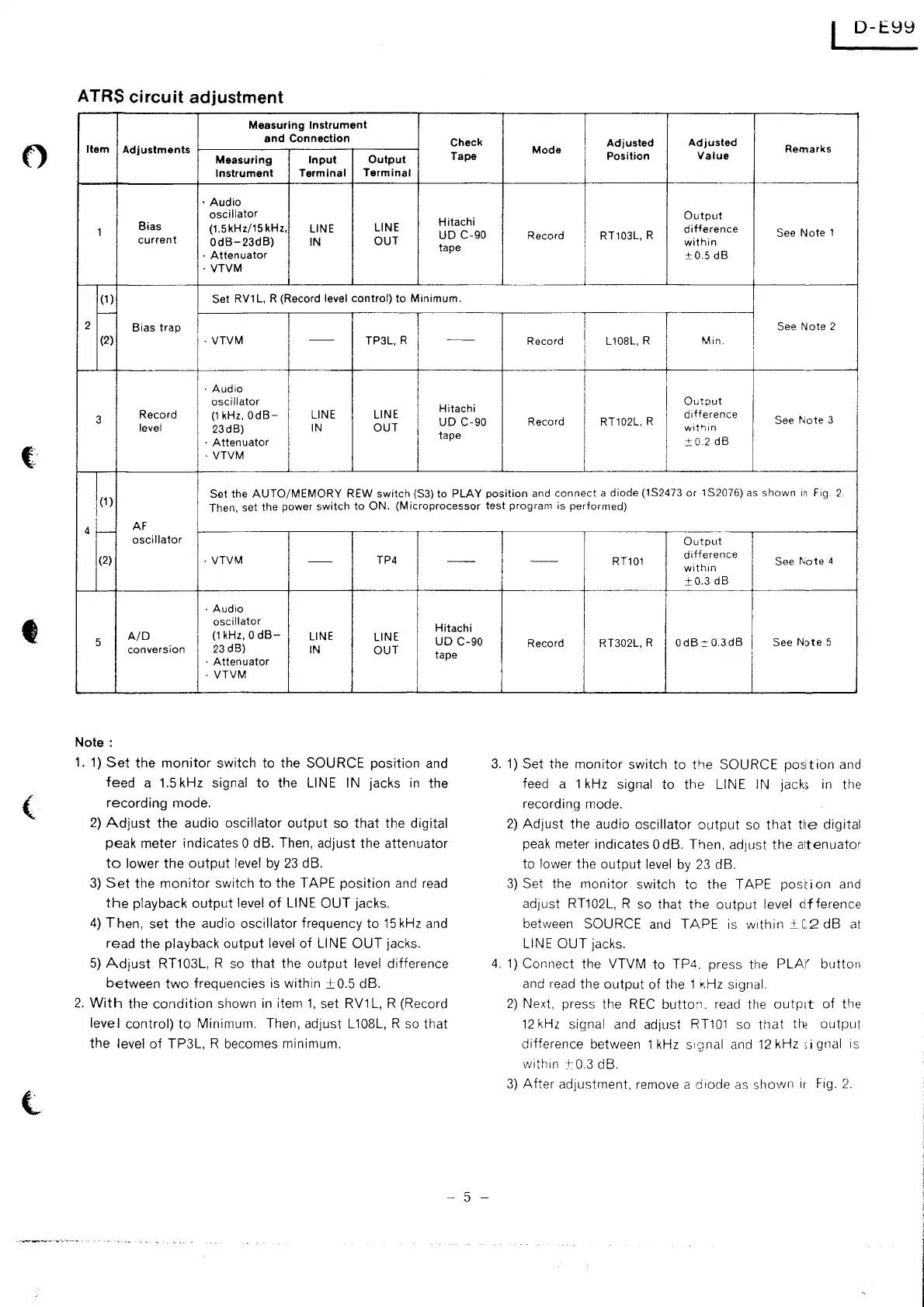
ATRS circuit adjustment
Measuring
Instrument
and
Connection
Check
Adjusted
Adjusted
Item
Adjustments
Tape
Mode
Position
Value
Remarks
Measuring
Input
Output
Instrument
Terminal
Terminal
·Audio
oscillator
Hitachi
Output
Bias
(1.5kHz/15kHz,
LINE
LINE
difference
1
UD
C-90
Record RT103L, R
See
Note
1
current
OdB-23dB)
IN
OUT
tape
within
·
Attenuator
±0.5
dB
·
VTVM
(1)
Set
RV1
L,
R (Record level
control)
to
Minimum.
-
2
Bias
trap
See
Note
2
(2)
·
VTVM
--
TP3L, R
--
Record
L 108L, R
Min.
I
I
·Audio
I
I
oscillator
Hitachi
I
Ou
tout
3
Record
(1
kHz,
OdB-
LINE
LINE
UD
C-90
Record
RT102L, R
difference
See
Note
3
level
23dB)
IN
OUT
wit'lm
·
Attenuator
tape
±0
2
dB
·
VTVM
I
Set
the
AUTO/MEMORY
REW
switch
(S3)
to
PLAY
position
and
connect
a
diode
(1S2473
or
1S2076) as
shown
in
Fig.
2.
(1)
I
Then, set
the
power
switch
to
ON.
(Microprocessor
test
program
is
performed)
4
>---
AF
oscillator
(2)
·
VTVM
--
TP4
--
·Audio
oscillator
Hitachi
5
A/D
(1
kHz, 0
dB-
LINE
LINE
UD
C-90
conversion
23d8)
IN
OUT
I
tape
·
Attenuator
·
VTVM
Note:
1.
1)
Set
the
monitor
switch
to
the SOURCE position and
feed
a
1.5
kHz signal
to
the LINE IN jacks
in
the
recording
mode.
2)
Adjust
the
audio oscillator
output
so
that
the digital
peak meter indicates 0 dB. Then, adjust the attenuator
to
lower
the
output
level
by
23
dB.
3)
Set
the
monitor
switch
to
the TAPE
position
and
read
the
playback
output
level
of
LINE
OUT
jacks.
4)
Then,
set
the
audio oscillator frequency
to
15
kHz and
read
the playback
output
level
of
LINE
OUT
jacks.
5)
Adjust
RT103L, R so
that
the
output
level difference
between
two
frequencies is within
±0.5
dB.
2.
With
the
condition
shown
in
item
1,
set RV1L, R (Record
level
control)
to
Minimum. Then, adjust L108L, R so
that
the
level
of
TP3L, R becomes minimum.
- 5 -
Output
I
--
RT101
difference
See
Note
4
within
I
±0.3
dB
Record RT302L, R
OdB::0.3dB
See
Note
5
i
3.
1)
Set the
monitor
switch to
the
SOURCE
position
and
feed a 1 kHz
signal
to
the
LINE IN jacks
in
the
recording mode.
2)
Adjust
the audio oscillator
output
so
that
He
digital
peak meter indicates 0 dB. Then, ad1ust
the
a1tenuator
to
lower the
output
level
by
23
dB.
3)
Set the
monitor
switch to the TAPE
position
and
ad1ust RT102L, R so
that
the
output
level
dfference
between SOURCE and
TAPE
is
within
±_C2
dB
at
LINE
OUT
jacks.
4.
1)
Connect the VTVM to TP4. press the
PLA(
button
and
read
the
output
of
the 1
KHz
signal.
2)
Next, press the
REC
butto:i.
read the outp:1t
of
the
12
kHz
signal and adjust
RT101
so
that
the
output
difference between 1
kHz
s1·2nal
and
12
kHz ;i gnal
1s
within
_+
0.3
dB.
3)
After
adjustment, remove a diode
as
shovvn
ir
Fig.
2.
 Loading...