ADJUSTMENT
Perform the following adjustments in the sequence stated after cleaning the heads, pressure rollers, and capstans with a head
cleaning stick moisted
in
alcohol. Also, unless otherwise specified, set the switches and controls
to
the positions indicated
in the
table.
(:''
Symbol
No.
Switches
and
Controls
Position Symbol No.
Switches
and
Controls
Position
S1
Input
select
switch
LINE
S2
Tape select switch
NOR-I
S3
Auto/memory
REW
switch
OFF
S4 Timer
switch
OFF
S5
Dolby
NR switch
OFF
S6
Dolby
NR
B/C
switch B
Measuring
Instrument
and
Connection
Check
Item
Adjustments
Measuring
Input
Output
Tape
Instrument
Terminal
Terminal
MTT-111,
1
Tape
· Frequency
--
LINE
3000
Hz
speed
counter
OUT
(3150
Hz*)
Tilt
and
·Head
(1)
height
of
adjusting
--
--
--
the head
jig
2
(2)
Head
· VTVM
--
LINE
MTT-114
azimuth
~:~TRI
(10kHz)
·Audio
Digital
oscillator
3
peak
(400
Hz)
LINE
--
meter
·
Attenuator
IN
·
VTVM
MTT-150,
4
Playback
· VTVM
TP2L, R
400
Hz,
gain
--
20m
Max-
well
Note:
1.
Adjust
within
30
sec.
after heat-running for more than
20
minutes.
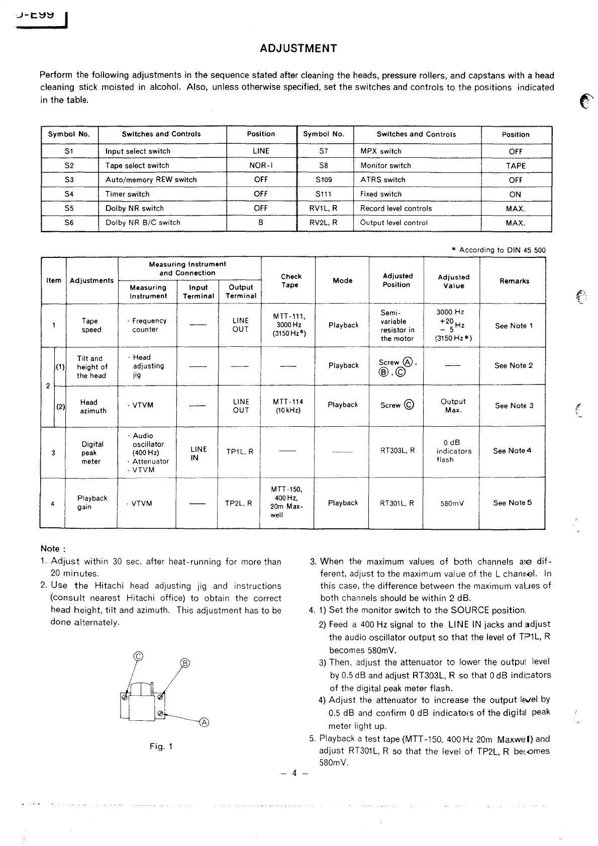
2.
Use
the
Hitachi
head
adjusting jig
and
instructions
(consult
nearest Hitachi office)
to
obtain the correct
head height,
tilt
and
azimuth. This adjustment
has
to
be
done alternately.
c
B
A
Fig.
1
- 4 -
S7
MPX switch
OFF
SB
Monitor
switch
TAPE
S109
ATRS
switch
OFF
S111
Fixed switch
ON
RV1L,
R Record level controls
MAX.
RV2L, R
Output
level control
MAX.
* According to
DIN
45
500
Adjusted
Adjusted
Mode
Remarks
Position
Value
Semi-
3000 Hz
Playback
variable
resistor in
+20H
- 5 z
See Note 1
the motor
(3150
Hz*)
Screw@,
Playback
--
See
Note 2
@.©
Playback
Screw©
Output
See Note 3
Max.
O
dB
--
RT303L, R
indicators
See
Note4
flash
--
Playback
RT301L, R
580mV
See
Notes
3.
When the maximum values
of
both channels are
dif-
ferent, adjust to the maximum value
of
the L channel.
In
this case, the difference between the maximum values
of
both channels should
be
within 2 dB.
4.
1)
Set the monitor switch
to
the SOURCE position.
2)
Feed
a
400
Hz signal
to
the LINE
IN
jacks and
adjust
the audio oscillator
output
so
that
the level
of
TP1L,
R
becomes
580mV.
3)
Then, adjust the attenuator
to
lower the output level
by
0.5
dB
and
adjust RT303L, R so that 0 dB indicators
of
the digital
peak
meter flash.
4)
Adjust
the attenuator to increase the
output
level
by
0.5
dB
and
confirm O dB
indicatms
of
the digital peak
meter
light up.
5.
Playback a test tape (MTT
-150,
400 Hz
20m
Maxwel
I)
and
adjust
RT301
L,
R so that the level
of
TP2L, R bec.omes
580mV.
I
\
 Loading...