EasyManua.ls Logo

Hitachi EH 5000AC-3 User Manual

Hitachi EH 5000AC-3
41 pages
To Next Page IconTo Next Page
Page #1 background imageLoading...
Page #1 background image
TOQHA-EN-00
EH5000AC
-3
RIGID DUMP TRUCK TECHNICAL MANUAL OPERATIONAL PRINCIPLE
PRINTED IN JAPAN (E) 2013, 02
Service Manual consists of the following separate Part No.
Technical Manual (Operational Principle) : Vol. No.TOQHA-EN
Technical Manual (Troubleshooting) : Vol. No.TTQHA-EN
Workshop Manual : Vol. No.WQHA-EN
TOQHA-EN-00
PART NO.
Rigid Dump Truck
Technical Manual
Operational Principle
URL:http://www.hitachi-c-m.com
5000AC
-3
EH
Question and Answer IconNeed help?

Do you have a question about the Hitachi EH 5000AC-3 and is the answer not in the manual?

Hitachi EH 5000AC-3 Specifications

General IconGeneral
BrandHitachi
ModelEH 5000AC-3
CategoryUtility Vehicle
LanguageEnglish

Summary

INTRODUCTION

To The Reader

Manual is for experienced technicians; read thoroughly for correct information.

Additional References

Refer to operator's manual, parts catalog, engine material, and training material.

Manual Composition

Details content of Technical, Workshop, and Engine Manuals for comprehensive service.

Page Number

Page numbers indicate manual type, section, group, and consecutive page within group.

Safety Alert Symbol and Headline Notations

Units Used

SECTION 1 GENERAL

Group 1 Machine Specifications

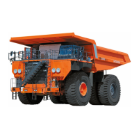
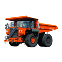
Provides detailed specifications for the EH5000AC-3 rigid dump truck.

Group 2 Component Layout

Illustrates and labels the various components and their locations on the machine.

Group 3 Component Specifications

Lists specifications for key components like Engine, Alternator, etc.

SECTION 4 OPERATIONAL PERFORMANCE TEST

SECTION 5 TROUBLESHOOTING

WORKSHOP MANUAL

SECTION 1 GENERAL INFORMATION

Covers general information, precautions, tightening, and periodic replacement of parts.

SECTION 2 BODY

Details components and layout related to the machine's body structure.

SECTION 3 HOIST DEVICE

Focuses on the hoist device components and their operation.

SECTION 4 AC DRIVE CONTROL DEVICE

Explains the AC drive control system components and functions.

Main Component Layout

Operator's Seat

Liquid Crystal Display (LCD)

Console Panel

Engine, Driving, and Hydraulic Indicators

Headlight, Front Combination Light/Horn Layout

Side Light Layout

Rear Light Layout

Maintenance Light Locations

Electrical Component Box (Behind Cab)

Fuse Box Layout

Relay Box Layout

Battery Relay Box Layout

Hydraulic Component: Main Pump System

Operator's Seat Environment

Front Axle Layout

Brake System Layout

Steering Cylinder Layout

Hoist Cylinder Layout

Suspension Cylinder and Rear Axle Housing

Wheel Reduction Device Cooling System

Control Cabinet (1) Layout

Control Cabinet (2) Layout

Terminal Board (TB3)-Output Connector

Breaker, Fuse, Relay, and Other Components

Auxiliary Alternator Field Regulator (AFR) Unit

Control Power (CS) Unit

Contactors, Relays, and Surge Absorber

Drive System Controller (DSC)

Rectifier (REC) Unit

Inverter (INV) Unit

Fan Unit

Related product manuals