SYSTEM DESCRIPTION
PMML0293A rev.2 - 08/2016
3
3 SYSTEM DESCRIPTION
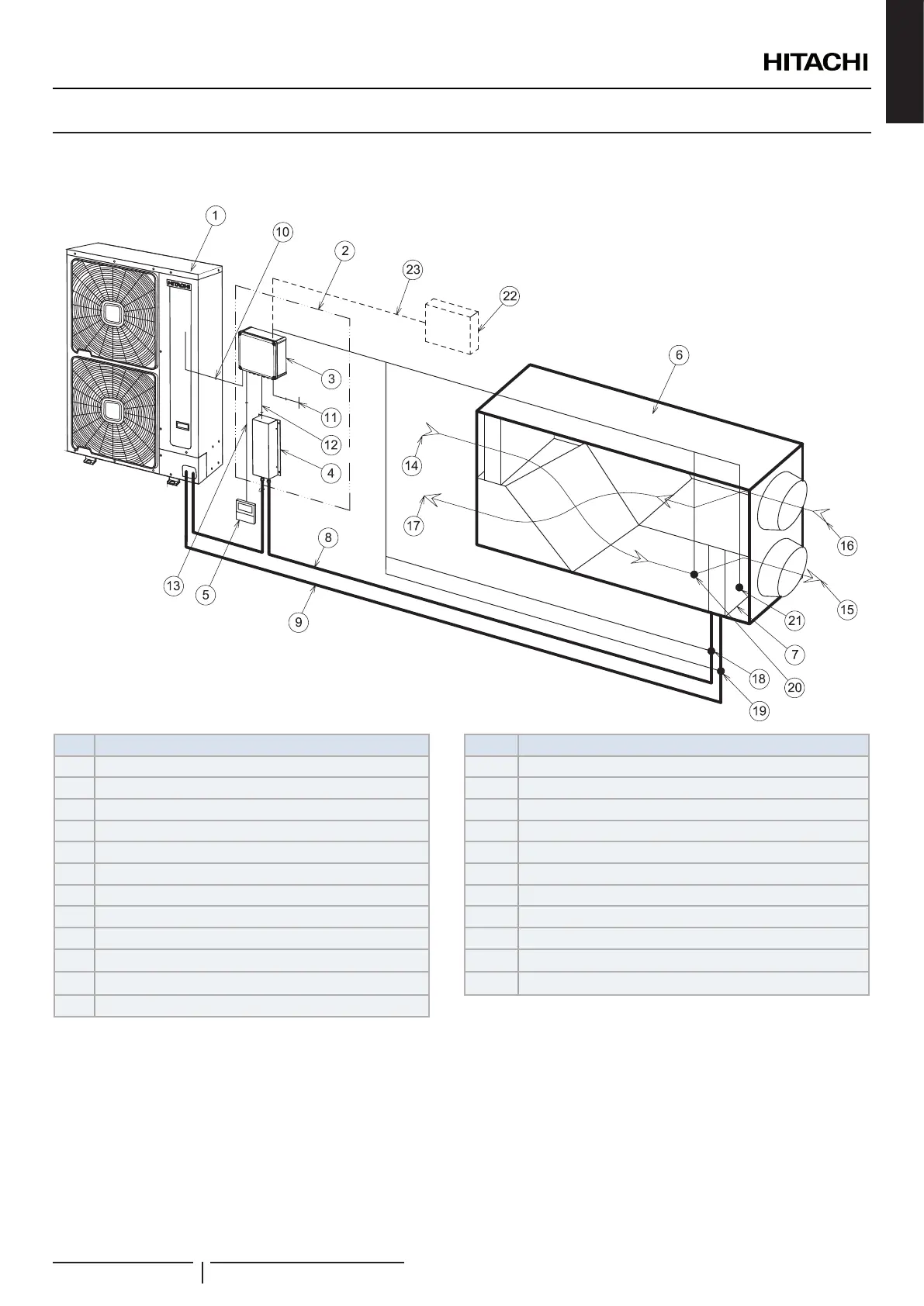
The following gure shows an installation example for air handling units (AHU).
Nº Description Nº Description
1 HITACHI outdoor unit 13 Remote controller communication
2 DX-Interface EXV-(2.0-10.0)E2 14 Outdoor air (AHU applications)
3 Control box 15 Supply air (AHU applications)
4 Expansion valve box 16 Return air (AHU applications)
5 Remote controller (Optional) 17 Exhaust air (AHU applications)
6 Unit or device with heat exchanger 18 Liquid pipe thermistor (THM3, PCB1)
7 DX- heat exchanger 19 Gas pipe thermistor (THM5, PCB1)
8 Liquid line 20 Inlet DX-coil thermistor (THM1, PCB1)
9 Gas line 21 Outlet DX-coil thermistor (THM2, PCB1)
10 Outdoor - Indoor communication 22 Field supplied controller (Optional)
11 Power supply 23 Duty signal (0~10V, 0~5V, 4~20mA) (Optional)
12 Expansion valve control communication
! CAUTION
• The installation distance between the DX-Interface and the device with heat exchanger must be the shortest possible.
• Keep the distance between the unit or device with heat exchanger and the expansion valve box for the piping length up to 5m. Also the elevation
difference between the unit or device with heat exchanger and the expansion valve box must be no more than 2m.
• Make sure that the installation distance between the control box and the unit or device with heat exchanger is short enough that the thermistors
sensing are not distorted.
• The thermistor cable should never be installed in the same ducting as power or control cables.
ENGLISH
 Loading...