EasyManua.ls Logo

Hitachi HGE 2100 User Manual

Hitachi HGE 2100
14 pages
To Next Page IconTo Next Page
Page #1 background imageLoading...
Page #1 background image
No.
338
EGF
HGE-2lOO
CONTENTS
.
INHALT
.
SOMMAIRE
SPECIFICATIONS
.
TECHNISCHE
DATEN
.
sPEC|FICAT|ONS....................
......................
1,2
FEATURES
.
MERKMALE
.
CARACTERISTIOUES....................
3
DISASSEMBLY AND REPLACEMENT.
ZERLEGUNG
UND
AUSTAUSCHE' DEMONTAGE
ET REMONTAGE.....................
3
ADJUSTMENTS
.
EtNSTELLVERFAHREN
.
RÉcr-ne
es...........
+
BLOCK D|AGRAM. BLOCKSCHEMA.
SCHEMA......................
4
PRINTED WIRING BOARD
.
PRINTPLATTEN
.
PLAN DE
84SE................
......... 5
CIRCUIT DIAGRAM
.
SCHALTPLAN
.
P|-AN
DE C!RCU|T...........
.........
6
REP]ACEMENT
PARTS LIST. ERSATZTEILLISTE.
TABLEAU DES PtECES....
..................................
7
FRONT
AND REAR PANET.VORDERE
UND HINTERE
BEOIENUNGSTAFEL. PANNEAUX
AVANT ET
ARRIERE....... 11
SAFETY
PRECAUTIONS
The following
precautions
should be observed
when
servicing.
1.
Since
many
parts
in the
unit
have
special
safety related
characteristics, always use
genuine
Hitachi's replacement
parts.
Especially
critical
parts
in the
power
circuit block
should
not be replaced with
other
makers.
Critical
parts
are
marked
with
A
in the
schematic
diagram and circuit board diagram.
2. Before
returning
a
repaired
unit
to
the
customer,
the service
technician must thoroughly test the
unit to ascertain
that
is
completely
safe
to
operate
without
danger
of electrical shock.
SPECIFICATIONS
lnput
sensitivity/
lmpedance
Rated
output/
lmpedance
Total
harmonic
distor-
tion
Frequency
response
Signal-to-noise
ratio
Equalizer
center fre-
quencies
MIC 1 mV/8
kohms
SOURCE/
TAPE
15O mY/47
kohms
150
mV/4 kohms
0.05%
(1V
output)
20Hz-2O kHz
-+2
dB
70
dB
(150
mV input)
9 elements
63 Hz, 125
Hz,25O
Hz, 5OO Hz,1 kHz,2k{z,4kHz,
8kHz,16kHz
Variable
range
of
adjust-
ment
Echo
time
Delay
time
MIC
jacks
Tape
systems
Power
supply
voltage
Power
consumption
Dimensions
Weight
-r
1O
dB
variablel
sec.-4sec.
variable
20 msec.
-
1OO
msec.
2
1
AC1
20V
60 Hz,
-22OV
50 Hz,
-24OV
50 Hz,
'l
10-120\l
|22O-24OV
50/60
Hz
10w
435
(W)x
83
(H)x
225
(D)
mm
3ks
*
All
specifications
for
this
unit apply
with
a flat equalization.
SPECIFICATIONS
AND PARTS
ARE
SUBJECTTO
CHANGE FOR
IMPROVEMENT.
GRAPHIC EOUALIZER
July
1982
TOYOKAWA
WORKS
Question and Answer IconNeed help?

Do you have a question about the Hitachi HGE 2100 and is the answer not in the manual?

Hitachi HGE 2100 Specifications

General IconGeneral
BrandHitachi
ModelHGE 2100
CategoryStereo Equalizer
LanguageEnglish

Summary

Safety Precautions

Servicing Safety Guidelines

Essential safety guidelines for servicing the equipment, emphasizing genuine parts and thorough testing.

Technical Specifications

HGE-2100 Specifications

Detailed technical parameters of the HGE-2100 graphic equalizer, including audio and power specifications.

Product Features

Key HGE-2100 Features

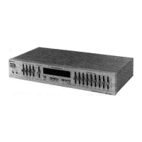
Highlights the equalizer's 9-band octave division, dynamic range inductors, electronic echo circuit, and convenient controls.

Disassembly and Replacement

Printed Wiring Board Removal Guide

Instructions and diagrams for removing printed wiring boards during disassembly, including screw specifications.

Adjustments and Calibration

BBD Output Clock Canceller Adjustment

Procedure to adjust R585 for eliminating BBD output clock elements, referencing oscilloscope waveforms.

Block Diagram

HGE-2100 Block Diagram

Visual representation of the HGE-2100's internal circuit connectivity and signal flow.

Safety Checks Before Return

Insulation Resistance Measurement

Method to measure insulation resistance between power supply plug and input terminal to ensure safety before customer return.

Printed Wiring Board Layout

Component Placement Diagram

Diagram illustrating the component layout on the printed wiring boards.

Circuit Diagram

Circuit Diagram Overview

Comprehensive schematic showing the electronic components and their interconnections within the HGE-2100.

Circuit Diagram Sections

MIC, REVERB, and EQ Circuitry

Detailed schematic breakdown of specific functional blocks like MIC AMP, REVERB, and EQUALIZER circuits.

Circuit Diagram - Power and Output

Power Supply and Output Filter Schematics

Schematic details for the power supply, muting circuit, and output filtering stages.

Replacement Parts List - Capacitors & Resistors

Capacitor Replacements

List of replacement capacitors with part numbers, descriptions, and specifications.

Resistor Replacements

List of replacement resistors with part numbers, descriptions, and specifications.

Replacement Parts List - Resistors (Continued)

Continued Resistor Replacements

Continuation of the replacement resistor list with part numbers and specifications.

Component Replacements - ICs, Transistors, Diodes

ICs and Transistors

List of integrated circuits and transistors with part numbers and descriptions.

Diodes and Variable Resistors

Replacement parts list for diodes and variable resistors, including part numbers.

Miscellaneous and Assembly Parts

Miscellaneous Components

List of miscellaneous parts like switches, jacks, fuses, and power switches.

Final Assembly Parts

Parts related to the final assembly, such as escutcheons, covers, and screws.

Assembly and Accessory Parts

Dial Mechanism Parts

Replacement parts for the dial mechanism, including sub panels, buttons, legs, and screws.

Rear Plate and Accessories

Parts for rear plate assembly (plates, cords, outlets) and accessories like patch cords.

Panel Identification and Controls

Front Panel Controls and Jacks

Identification and description of front panel controls, switches, and input/output jacks.

Rear Panel Connectors and Controls

Identification and description of rear panel connectors, power cord, and voltage selector.