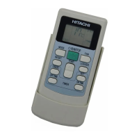
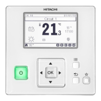
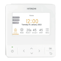
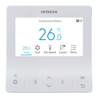
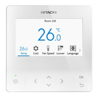
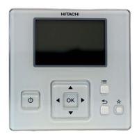
INSTALLATION OF REMOTE CONTROL SWITCH <PC-2H2>
4
1.4.3. ONE REMOTE CONTROL SWITCH FOR
MULTIPLE UNITS
This remote control switch can control sixteen units, as the
maximum.
In case of this modification, wiring connection and other works
shall be performed as indicated in the following procedures.
Wiring Connection for Control Circuit
Fig. 13 Wiring connection
1. The power source cable and the bridge cable between the
indoor unit(s) and the outdoor unit(s) should be performed
in accordance with the installation manual of the unit.
2. The cables (0.3 mm
2
wire) of different length are prepared
as an option, which are fitted with connectors.
Cable Model PRC-10E PRC-15E PRC-20E PRC-30E
Length (m) 10 15 20 30
In case that a longer cable is required, the additional field-
supplied cable shall be connected as following procedure.
A. Prepare the cable with two wires.
B. After checking the color of the wires, connect each wire
of the same color by soldering.
C. Insulate the soldered parts and the wires with insulation
tape.
D. The maximum total cable length of the remote control
switch cable and the bridge cable(s) is 200
meters(0.3mm2 wire) or 500 meters(0.75mm2 wire).
3. Separate the cable more than approximately 30cm from
any wires which are utilized for wires higher than 220V, or
put the cable in a metal tube and earth the tube.
4. Set the serial unit number by adjusting the “DSW” dip
switch on the printed circuit board(s) in the indoor unit(s).
This setting should be matched with the serial number of
the bridge cable(s).
Setting of dip switch:
)
))
) )
))
) )
) )
) )!
)!)!
)!
OFF
ON
OFF
ON
OFF
ON
OFF
ON
)"
)")"
)" )#
)#)#
)# )$
)$)$
)$ )%
)%)%
)%
OFF
ON
OFF
ON
OFF
ON
OFF
ON
)&
)&)&
)& )'
)')'
)' ))
))))
)) )>
)>)>
)>
OFF
ON
OFF
ON
OFF
ON
OFF
ON
)+
)+)+
)+ )@
)@)@
)@ )-
)-)-
)- ).
).).
).
OFF
ON
OFF
ON
OFF
ON
OFF
ON
Connector
Red
Black
Red
Black
Connector
Field-Supplied
Wir
l
AW
22~AW
2
Cable of Remote
Control Switch
Printed Circuit Board
in the Indoor Unit
Main (A0)
Branch 1 (A1) Branch 2 (A2)
Bridge Cables (3 Wires or 2 Wires)
Yellow
Blue
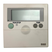
Remote Control Switch
 Loading...


