2.2 BEFORE INSTALLATION
Check the contents and the number of the accessories in the packing.
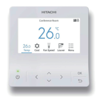
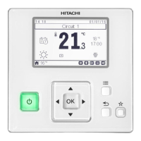
A/C
COOL
HIGH
LOUV.ADJ
Meeting Room
MODE SPEED LOUV. TEMP
FLTR
Motion Sensor is activated
OK
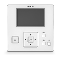
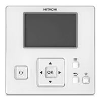
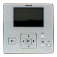
Remote control switch for
operation control
2 screws M4x16L for xing the
holding bracket onto the wall
1 Operation Manual
2.3 INSTALLATION SPACE
In case of installing the controllers in vertical line, keep a
distance more than 50mm between the controllers vertically.
If the distance is insucient, the controller can not be taken out.
>
2.4 INSTALLATION PROCEDURES
1 Insert the edge of the slotted screwdriver into the groove at
the bottom of the holding bracket, push and turn the slotted
screw driver and then remove the remote control switch from
the holding bracket.
Groove part
Approx.
6mm
Figure seen from bottom side
Slotted
Screw driver
Rear
cover
Groove for attaching
controller
2 Attach the remote control switch to the holding bracket and
connect the cable as follows:
- In Case of Exposing Remote Control Cable
Fix the holding bracket onto the wall with screws
(accessory).
Attach the stopper (plastic band) to the cable at the
inside of the draw-out hole.
Cable
Band stopper
(Field-supplied)
Draw-out hole
Lead the cable with its
sheath peeled through
the groove.
Peel the insulation at
the end of the cable and
clamp the M3 solderless
terminals (field-supplied).
Lead the cable with its sheath
peeled through the groove.
Peel the insulation at the
end of the cable and clamp
the M3 solderless terminals
(eld-supplied).
- When Using Switch Box
a. Prepare eld-supplied Implanted Switch Box
(JIS Box). (JIS C 8336-1988)
The following 5 types are available.
1. Switch Box for 1 Switch (Without Cover)
2. Switch Box for 2 Switches (Without Cover)
3. Switch Box for 1 Switch (With Cover)
4. Switch Box for 2 Switches (With Cover)
5. Outlet Box (With Cover)
INSTALLATION WORK
PMML0404A rev.1.1 - 06/2022
2
 Loading...