b. Lead the cable through the conduit tube in the wall.
Implanted switch box
(JIS Box) for 2 switches
Implanted switch box
(JIS Box) for 1 switch
M4 screws
(eld-supplied)
c. Peel the insulation at the end of the cable and clamp the
M3 solderless terminals (eld-supplied).
Connect the terminals
3 Attach the remote control switch to the holding bracket. Be
careful not to pinch the cable when attaching it.
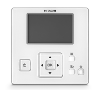
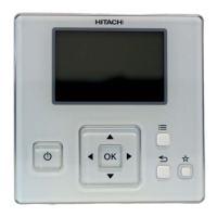
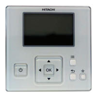
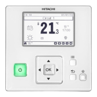
4 Remove the protection lm from the liquid crystal display.
Remove the protection lm
3 ELECTRICAL WIRING
Wiring Example (Using a twist pair cable with shield tube)
REMOCON
A
REMOCON
B
REMOCON
A
REMOCON
B
AA
BB
Max 16 indoor units
Remote
control switch
Remote control
switch
(Subsidiary)
Electrical box
of indoor unit
Electrical box
of indoor unit
Terminal board
Terminal board
M3.5
screws
M3.5
screws
M3
screws
Twist pair cable with shield tube: 1P-0.75mm
2
or more
! CAUTION
Always make sure to turn off the power of the indoor unit when performing
electrical wiring work. Performing electrical wiring work with the power on
can damage the circuit boards of the indoor unit and the remote control
switch.
• Remote control cable <option> Model: PRC-x K
Twist pair cable (1P-0.75mm
2
)
50mm
100mm
Solderless Tern (X Type)
1.25-3X
Diameter: Ø 7
Color: Ivory
The number of x indicates the length (m) of the cable (x=2, 3, 5,
8, 10, 15, 20, 30, 50, 75, 100).
The cable of 30m and over is available by ordering.
? NOTE
• Use a 0.3 to 0.75mm
2
cable for connecting. The maximum
total cable length is 30m. If the total cable length exceeds
30m, use a twist pair cable with shield tube (1P - 0.75mm
2
).
In that case, the maximum total cable length is 500m.
If using in combination with the control timer, the allowable total cable
length is up to 100m. The use of a cable other than that specied
above can cause of malfunction due to effects of noise.
• Keep a distance more than 30cm between the transmission line
(remote control switch cable and transmission wires) and power
source of the indoor units. If not, the air-conditioner may not operate
properly or malfunction may occur due to effect of power source
noise.
• In case of simultaneously controlling multiple indoor units, set the
refrigerant cycle numbers and addresses of the indoor units without
overlapping.
• Refer to the Technical Catalog provided with each indoor unit when
performing electrical wiring work between the remote control switch
and indoor units for setting the refrigerant cycle number and the
indoor unit address.
• No gap shall exist between the remote control switch cable and hole
of the remote control switch case. If there is a gap, cover the gap
with vinyl tape. If not, malfunction may occur due to entrance of water
droplets or insects.
• In case of operating with two remote control switches (Main and
Sub), set the main and sub remote control switches by selecting the
appropriate function with the remote control switches according to
the chapter “6 Function Selection and setting”. After setting it, turn
off the power supply of all the indoor unit connected to the remote
control switches.
• The control timer cannot be used together with this remote control
switch.
ENGLISH
ELECTRICAL WIRING
PMML0404A rev.1.1 - 06/2022
3
 Loading...