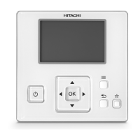
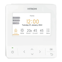
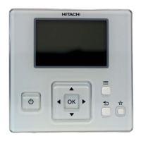
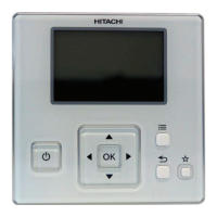
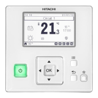
4 SWITCH NAMES AND FUNCTIONS
The gure below shows all the indications for reference. The actual display during operation is dierent.
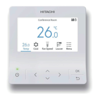
Display Part
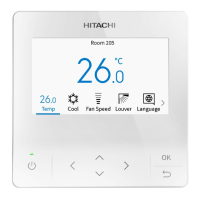
A/C
COOL
HIGH
LOUV.ADJ
Meeting Room
MODE SPEED LOUV. TEMP
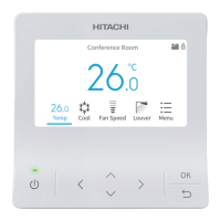
FLTR
Motion Sensor is activated
OK
Filter Sign Indicator
It is indicated at the set period for lter
cleaning.
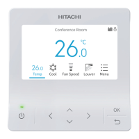
Operation Lock Indicator
It is indicated when the operation lock
function is set.
Schedule Timer Indicator
It is indicated when the schedule timer
function is set.
Swing Louver
Indicator
Fan Speed Indicator
Arrow Key Enter Key
RUN/STOP Switch
Run Indicator
It lights while the unit is
operated, and it ashes in
an abnormal conditions.
Operation Mode
Indicator
The indications of “HEAT”
and “AUTO” are indicated
only for the heat pump type
models.
Operation Guide
Indicator
“Central Control” is
indicated while the remote
control operation is
prohibited.
Room Name
Indicator
Operation Part
Setting Temperature
Indicator
Help Switch
To display Help Menu.
Return Switch
To return to the previous
screen.
Menu Switch
To display Menu.
Motion Sensor Indicator
It is indicated only for the air
panel with motion sensor.
? NOTE
• Do NOT press the switches hard or press with sharply pointed material such as a ball point pen. The operation part of the remote control switch
may be damaged.
• Make sure that the switches are pressed softly with ngers.
SWITCH NAMES AND FUNCTIONS
PMML0404A rev.1.1 - 06/2022
4
 Loading...