g. 2
g. 3
Fig.4
(5) Remove the electrical box fixing screws and
ND wire fixing
w
Remove P
w
n
w
r
.
et the electrical box u
side down.
Remove
.
.B.
ixing screws (2 locations) and radiation
in
ixing
screws
locations
, and remove the
.
.
rom t
e su
ort.
1. Electr
cal Part
1
emove t
e upper cover
x
ng screws an
t t
e cover to remove
t.
2
Remove the service valve cover
3
Remove the terminal
late cover
(4) Remove the right side cover
Radiation fin fixing screw
P.W.B. fixing screw
g. 1
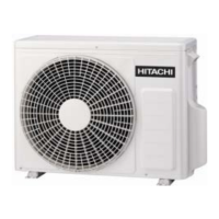
MODEL RAC-18/25WP<OUTDOOR UNIT>
7
C
right side cover.
terminal cover.
valve cover.
Procedure for Disassembly and Reassembly

 Loading...