Do you have a question about the Hitachi RAC-35WPB and is the answer not in the manual?
| Cooling Capacity | 3.5 kW |
|---|---|
| Heating Capacity | 4.0 kW |
| Refrigerant | R410A |
| Power Supply | 220-240V, 50Hz |
| Weight (Indoor Unit) | 10 kg |
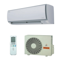
| Type | Split Air Conditioner |
| Noise Level (Outdoor) | 52 dB(A) |
Defines the applicability of semiconductor handling standards.
Lists semiconductor components covered by the standards.
Provides guidelines for safe handling of semiconductor parts.
Instructions for initial setup of the remote controller, including battery installation and mounting.
Overview of the remote control unit's range and handling.
Button to start or stop the air conditioner operation.
Button to adjust the fan speed settings.
Button to activate the energy-saving ECO operation mode.
Explains how the unit automatically selects heating or cooling mode based on room temperature.
Describes the unit's behavior after a power failure, resuming previous operation.
Button to cycle through operating modes like AUTO, HEAT, COOL, FAN.
Button to activate the maximum power operation mode.
Button to set the unit to silent operation mode.
Button to set the unit for unoccupied home operation.
Button to set the ECO sleep timer function.
Button to set the sleep timer function.
Explains the defrosting process that occurs during heating operation.
Details how the unit performs dehumidification based on room temperature.
Steps to initiate the vertical auto swing function for the air deflector.
Instructions to activate the maximum power operation mode.
Steps to activate the silent operation mode for reduced fan noise.
Instructions to activate the energy-saving ECO operation.
Steps to set the unit for maintaining a minimum temperature when the home is unoccupied.
Instructions to initiate the self-cleaning cycle for the indoor heat exchanger.
Instructions for setting the unit to turn off at a specific time.
Instructions for setting the unit to turn on at a specific time.
Steps to activate the ECO sleep timer for energy saving.
Detailed steps for programming a weekly timer schedule for the unit.
How to view the ambient temperature measured by the remote controller.
Steps to display the unit's monthly power consumption data.
Procedure to lock the remote controller to HEATING mode only.
Identifies and describes the components of the indoor unit.
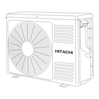
Identifies and describes the components of the outdoor unit.
Instructions for cleaning and maintaining the air filter.
Steps for cleaning the front panel of the indoor unit.
Details the heating, cooling, and dehumidifying capabilities of the unit.
Information regarding after-sales service and warranty conditions.
Provides detailed dimensions and construction diagrams for the indoor unit.
Provides dimensions and construction for the outdoor unit (RAC-18/25WPB).
Provides dimensions and construction for the outdoor unit (RAC-35WPB).
Provides dimensions and construction for the outdoor unit (RAC-50WPB).
Lists thermostat specifications for different models and operation modes.
Provides specifications for the fan motor, including output and connection details.
Details the specifications for the compressor motor, including resistance values.
Wiring diagram for the outdoor unit.
Steps for disassembling and reassembling the indoor unit's front panel and covers.
Explains the operation of the control power circuit, including fuse and varistor functions.
Details the function of the reset circuit for initializing the microcomputer.
Explains the operation and components of the indoor fan motor drive circuit.
Explains the circuit that receives signals from the remote control.
Explains the function and settings of the dip switches.
Describes the communication circuits between indoor and outdoor units.
Details the main power circuit, including key components like IPM and diode stacks.
Explains the low voltage power supply circuits for various components.
Describes the control circuit for the reversing valve in different operation modes.
Explains the circuits that detect indoor and outdoor temperatures.
Details the circuit for controlling the electric expansion valve.
Explains the control circuit for the outdoor DC fan motor.
Guidelines for performing inspections when troubleshooting the unit.
Steps for removing electrical components from the indoor unit.
Procedure for removing the main control printed wiring board.
Critical warning against handling connectors while the unit is powered.
How to interpret self-diagnosis information displayed by the indoor unit's timer lamp.
How to interpret self-diagnosis information indicated by the outdoor unit's LD301 lamp.
Information on how the unit stores and retrieves failure modes.
Describes the function of the temporary operation switch for manual control.
Initial diagnostic steps.
Steps to troubleshoot indoor unit electrical issues.
Diagnostic steps for when the unit does not power on.
Diagnostic steps for when the remote control signal is not received.
Interference from lighting.
Interference from other remotes.
Diagnostic steps for compressor not running.
Diagnostic steps for fan motor not stopping.
Diagnostic steps for 9 blinks.
Diagnostic steps for 10 blinks.
Diagnostic steps for 12 blinks.
Procedure to troubleshoot issues related to refrigerating cycle problems.
Part list and exploded diagram for the RAK-18/25PPB indoor unit.
Part list for the RAK-35/50PPB indoor unit.
Part list and exploded diagram for the RAC-18/25WPB outdoor unit.
Part list and exploded diagram for the RAC-35WPB outdoor unit.
Part list and exploded diagram for the RAC-50WPB outdoor unit.