OUTDOOR UNIT
● Please mount the Outdoor unit on stable ground to prevent
vibration and increase of noise level.
● Decide the location for piping after sorting out the different types
of pipe available.
● When removing side cover, please pull the handle after undoing
the hook by pulling it downward.
<IA1575: B >
Preparation of Pipe
1
● Use a pipe cutter to cut
the copper pipe.
● Jagged edge will cause leakage.
● Point the side to be trimmed downwards during trimming to prevent
copper chips from entering the pipe.
● Before fl aring, please put on the fl are nut.
Pipe Connection
2
INSTALLATION OF REFRIGERATING PIPES AND AIR REMOVAL
CAUTION
!
Please face this side (suction side)
of the unit to the wall.
Please remove side cover
when connecting the piping and
connecting cord.
Pull downward
BASE
● Recommend to use
R32 fl aring tool.
CAUTION
!
●
When removing fl are nut from the Indoor unit, please
ensure to use proper tooling.
●
Prevent pipe from coming in contact with water or
working in wet area.
CONDENSED WATER DISPOSAL OF OUTDOOR UNIT
● There are holes on the base of Outdoor unit for condensed
water to exhaust.
● In order to fl ow condensed water to the drain, the unit is installed
on a stand or a block so that the unit is 100mm above the ground
as shown fi gure. Join the drain pipe to one hole.
● At fi rst insert one portion of the hook to the base (Portion A),
then pull the drain pipe in the direction shown by the arrow while
inserting the hook into the base. After installation, check whether
the drain pipe cling to the base fi rmly.
When Using and Installing In Cold Areas
When the air conditioner is used in low temperature and in snowy
conditions, water from the heat exchanger may freeze on the base
surface to cause poor drainage. When using the air conditioner
in such areas, do not install the bushings. Keep a minimum of
250mm between the drain hole and the ground. When using the
drain pipe, consult your sales agent.
For more details, refer to the installation Manual for Cold Areas.
DRAIN PIPE
100 mm ABOVE
BUSH
BUSH
DRAIN PIPE
Trimming tool
Copper pipe
Die
Die
Copper pipe
Flare nut
Torque
wrench
Wrench
Removal Of Air From The Pipe And Gas Leakage Inspection
Gas Leakage Inspection
Please use gas leakage detector
to check if leakage occurs at the
connection of Flare nut as shown
on the right.
If gas leakage occurs, further
tighten the connection to stop
leakage. (Be sure to use R32
detector)
3
AIR REMOVAL
When the meter reaches - 101KPa
(-76cmHg) during pumping, fully tighten
the shuttle.
Closed
R32
Valve
Charge hose
Vacuum
pump
adapter
When pumping starts, slightly loosen
the fl are nut to check of air sucked in.
Then tighten the fl are nut.
Vacuum
pump
Manifold valve
Meter showing pressure
Valve
Procedures of using Vacuum Pump for Air Removal
As shown in right fi gure, remove the cap of
valve core. Then, connect the charge hose.
Remove the cap of valve head. Connect the
vacuum pump adapter to the vacuum pump
and connect the charge hose to the adapter.
Fully tighten the “Hi” knob of the manifold
valve and completely unscrew the “Lo” knob.
Run the vacuum pump for about 10~15
minutes, then completely tighten the “Lo” knob
and switch off the vacuum pump.
2
Completely unscrew the spindle of the
service valve (at 2 places) in anti-clockwise
direction to allow the fl ow of refrigerant (using
Hexagonal Wrench key).
Re-cap the service valve and tighten using
wrench. Check the cap’s periphery if there is
any gas leakage. The task is then completed.
Remove the charge hose and tighten the cap
of valve core. Check the cap’s periphery if
there is any gas leakage.
4
5
1
3
Cap of valve head
Cap of valve head
The body of
service valve
Hexagonal
Wrench Key
Cap of valve
core
Outer
Diameter
mm (inch)
6.35 (1/4")
9.52 (3/8")
12.70 (1/2")
15.88 (5/8")
1.0 ~ 1.5
1.0 ~ 1.5
1.0 ~ 1.5
1.0 ~ 1.5
Clutch type
A (mm)
1.5 ~ 2.0
1.5 ~ 2.0
1.5 ~ 2.5
1.5 ~ 2.5
Wing nut type
Thickness
(mm)
0.8
0.8
0.8
1.0
0.0
~ 0.5
0.0
~ 0.5
0.0
~ 0.5
0.0
~ 0.5
Flare tool for R32
Clutch type
Conventional fl are tool
Outer
dia.of pipe
6.35 (1/4")
9.52 (3/8")
12.70 (1/2")
15.88 (5/8")
6.35 (1/4")
9.52 (3/8")
12.7 (1/2")
15.88 (5/8")
Valve
head cap
Torque N·m
(kgf
·
cm)
14.0 – 18.0 (140 ~ 180)
33.0 – 42.0 (330 ~ 420)
50.0 – 62.0 (500 ~ 620)
63.0 – 77.0 (630 ~ 770)
19.6 – 24.5 (200 ~ 250)
19.6 – 24.5 (200 ~ 250)
29.4 – 34.3 (300 ~ 350)
29.0 – 31.0 (296 ~ 316)
12.3 – 15.7 (125 ~ 160)
Small dia. side
Large dia. side
Valve core cap
Small dia. side
Large dia. side
●
Prevent moisture from entering pipe
connection.
●
Refrigerating machine oil not be applied to
the outside of the fl are.
When refrigerating machine oil is applied to
the outside of the fl are, excessive tightening
of the fl are nut, cracking of the fl are nut,
destruction of the fl are and gas leakage may
occur.
●
When using the control valve, do not use
deteriorated packing. And, do not overtighten
the steering wheel.
Gas leakage from the service valve part,
stagnation, touching fi re, rarely cause ignition.
CAUTION
CONNECTION OF POWER CORD
Procedures of Wiring
Indoor Unit
Outdoor Unit
Detail of Cutting the Connecting Cord
Connecting cord
Outdoor Unit
Indoor Unit
Power line
Green + Yellow
(ground)
Green + Yellow
(ground)
Connecting cord
Connecting cord
Strip wires
Strip wires
Green + Yellow
● The naked part of the wire core should be 10 mm and fi x it to the terminal
tightly. Then try to pull the individual wire to check if the contact is tight.
Improper insertion may burn the terminal.
● Be sure to use only wire specifi ed for the use of air-conditioner.
● Please refer to the manual for wire connection and the wiring technique
should meet the standard of the electrical installation.
● There is an AC voltage drop between the LN terminal if the power is
on. Therefore, be sure to remove the plug from its socket.
WARNING
!
!
● Leave some space in the connecting
cord for maintenance purpose and
be sure to secure it with the cord
band.
● Secure the connecting cord along
the coated part of the wire using the
cord band. Do not exert pressure
on the wire as this may cause
overheating or fi re.
Wiring of The Outdoor Unit
● Please remove the side plate for wire connection.
WARNING
● If you cannot attach the side plate due to the connection cord, please press the connecting cord in
the direction to the front panel to fi x it.
● Be sure that the hooks of the side plate is fi xed in certainly. Otherwise water leakage may occur
and this causes short circuit or faults.
● The connecting cord should not touch to service valve and pipes. (It becomes high temperature in
heating operation.)
● Before installation, the power source must be checked and necessary wiring work must be completed. To make
the wiring capacity proper, use the wire gauge list below for the wiring from house distribution fuse box to the
outdoor unit in consideration of the locked rotor current.
● Investigate the power supply capacity and other electrical conditions at the
installing location.
Depending on the model of room air conditioner to be installed, request the
customer to make arrangements for the necessary electrical work etc.
The electrical work includes the wiring work up the outdoor unit . In
localities where electrical conditions are poor, use of a voltage regulation
is recommended.
● Install outdoor for the room air conditioner within the reaching range of the
line cord.
Earth terminal
Outdoor supply cords shall not be lighter
than polychloroprene sheathed fl exible
cord with code designation 60245 IEC 57.
Wire length
up to 30 m
Wire cross-section
1.5mm
2
For (Connecting cord - 1, 2, 3, Earth)
Wire cross-section
2.5 mm
2
For (Power cord - L, N, Earth)
WARNING
● THIS APPLIANCE MUST BE EARTHED.
Power cord
Checking for the electric source and the voltage range
Cover
CAUTION
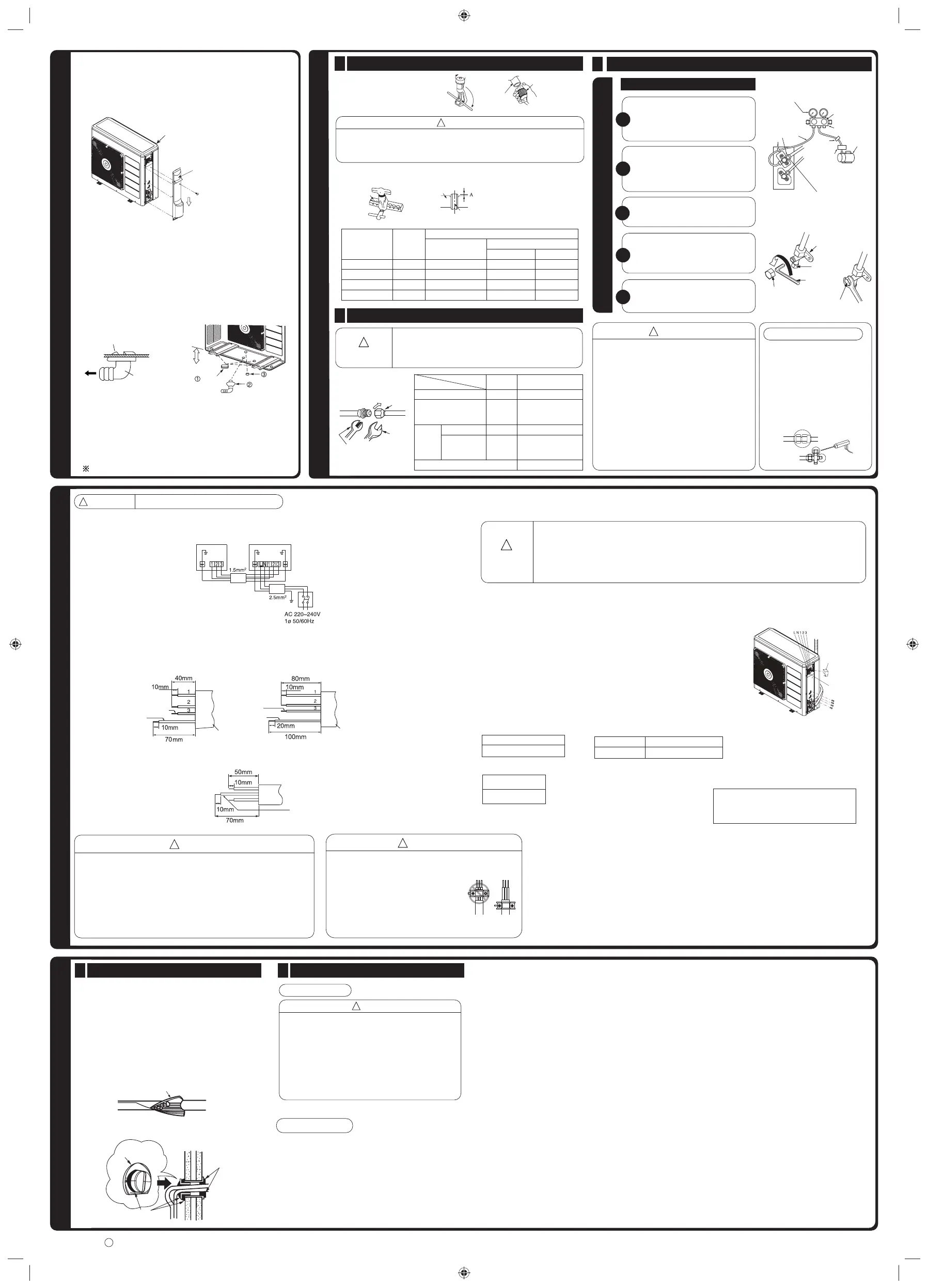
FINAL STAGE OF INSTALLATION
Insulation And Maintenance Of Pipe Connection
1
● The connected terminals should be completely sealed
with heat insulator and then tied up with rubber strap.
● Please tie the pipe and power line together with vinyl
tape as shown in the fi gure showing the installation of
Indoor and Outdoor units. Then fi x their position with
holders.
● To enchance the heat insulation and to prevent water
condensation, please cover the outdoor part of the drain
hose and pipe with insulation pipe.
● Completely seal any gap with putty.
Power Source And Operation Test
2
Power Source
CAUTION
!
● Please use a new socket. Accident may occur due
to the use of old socket because of poor contact.
● Please plug in and then remove the plug for 2 – 3
times. This is to ensure that the plug is completely
plugged into the socket.
● Keep additional length for the power cord and do
not render the plug under external force as this
may cause poor contact.
● Do not fi x the power cord with U-shape nail.
Operation Test
● Please ensure that the air conditioner is in normal
operating condition during the operation test.
● Explain to your customer the proper operation
procedures as described in the user’s manual.
Insulation material for pipe connection
Putty
Putty
Sleeve of
protection pipe
!
IMPORTANT
Circuit Breaker
20A
 Loading...