Do you have a question about the Hitachi RAI-50NH5 and is the answer not in the manual?
Detailed technical specifications for the room air conditioner model.
Essential safety guidelines for service personnel before and during unit repair.
Standards for handling semiconductors to prevent damage during maintenance.
Important warnings and cautions for safe operation and maintenance of the unit.
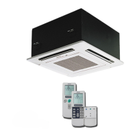
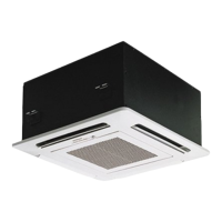
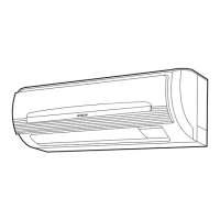
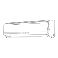
Identification and function of key components within the indoor unit.
Explanation of indoor unit indicator lamps and the temporary operation switch.
Guide to using the remote controller and important usage precautions.
Explanation of auto restart control and automatic operation modes.
Instructions for operating the unit in heating mode, including temperature and fan speed settings.
Instructions for operating the unit in dehumidifying mode, including temperature and fan speed.
Instructions for operating the unit in cooling mode, including temperature and fan speed.
Instructions for operating the unit in fan-only mode for air circulation.
Procedures for setting ON/OFF timers and canceling timer reservations.
How to adjust the horizontal air deflector for optimal airflow direction.
Step-by-step guide on how to replace batteries in the remote controller.
Recommendations for optimal room temperature, ventilation, and timer use.
Information on heat sources in the room and precautions for extended non-operation or lightning.
Detailed instructions for removing, cleaning, and installing the air filter.
Guidelines for cleaning the front panel and maintenance before long periods of non-operation.
Information on what to check before requesting service and warranty details.
Diagrams showing indoor unit dimensions, installation clearances, and piping specifications.
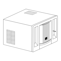
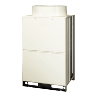
Diagrams detailing outdoor unit dimensions and required service space for installation.
Specifications for the thermostat and fan motor, including operating modes and connection details.
Specifications for the compressor motor, including phase, voltage, frequency, and connection.
Complete wiring diagrams illustrating connections for indoor and outdoor units.
Detailed circuit diagram for the remote control unit and its components.
Location diagrams for components on the main printed wiring board (PWB) for both sides.
Overall system block diagram showing the interaction between indoor and outdoor units and microcomputers.
Explanation of how the unit operates in auto mode, including fan speed and temperature control.
Analysis of cooling operation, including temperature differences and compressor speed calculations.
Analysis of dehumidifying operation, including fan speed and compressor control during temperature variations.
Details on defrosting cycles and sleep mode operations for optimal performance.
Diagrams illustrating the refrigerating cycles for cooling, heating, and defrosting modes.
Explanation of how to use the auto swing function for air deflector movement.
Description of the reset circuit's function in initializing the microcomputer program.
Explanation of the receiver circuit for remote signals and the buzzer circuit's functionality.
Details on the auto sweep motor drive circuit and microcomputer output signals.
Explanation of room and heat exchanger temperature thermistor circuits and their voltage outputs.
Operation of the initial setting circuit for reading data from E2PROM for setup.
Description of the power circuit for the PWB, including active module and diode stacks.
Explanation of the interface circuit enabling communication between indoor and outdoor microcomputers.
Explanation of the drive circuit for U, V, and W phases of the compressor motor.
Description of the reversing valve control circuit and its collector voltage readings during operation.
Circuitry for detecting rotor magnetic pole position and drive signals for the compressor motor.
Explanation of the system power module circuit and its peripheral components.
Explanation of circuits for detecting over-heat, defrost, and outdoor temperatures using thermistors.
Detailed description of the reset circuit's function and waveform behavior during power on/off.
Explanation of the control circuit for the outdoor DC fan motor, including speed and fault detection.
Information on controlling power factor to nearly 100% for effective power usage.
Frequently asked questions and answers to help diagnose common operational problems.
Safety precautions and measurement guidelines for troubleshooting electrical parts.
Guide to diagnosing issues based on indoor timer lamp and outdoor LD301 blink patterns.
Step-by-step checks for indoor unit electrical parts when power is not received.
Troubleshooting outdoor unit operation issues when it receives remote signals but does not operate.
Checks for indoor fan operation, speed changes, and air deflector movement issues.
Diagnosing and resolving issues where all systems stop shortly after operation begins.
Procedures for checking battery polarity, remote control signals, and LED indicators.
Steps to check outdoor unit power supply, fuses, and voltage outputs for troubleshooting.
Diagnosing communication errors indicated by LD301 blinking 9 times, focusing on interface circuits.
Diagnosing errors related to power module, drive circuit, and thermistor faults based on LD301 blink codes.
Diagnosing errors related to switching failures, abnormal low speed, and temperature rise.
Troubleshooting why rotation speed does not increase, checking DC voltage and OVL lamp status.
Procedures for checking gas pressure, identifying leaks, and diagnosing compressor defects.
Method for testing the conductivity of the system power module using a tester.
How to operate the outdoor unit independently using the service switch and for testing.
Circuit diagrams and terminal markings for diagnosing the system power module.
Exploded view and parts list for the RAI-ECPM indoor unit assembly.
Exploded view and parts list for the RAI-50NH5 indoor unit components.
Exploded view and parts list for the RAC-50NH5 outdoor unit components.
| Brand | Hitachi |
|---|---|
| Model | RAI-50NH5 |
| Category | Air Conditioner |
| Language | English |