SPECIFICATIONS AND PARTS ARE SUBJECT TO CHANGE FOR IMPROVEMENT
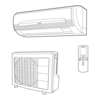
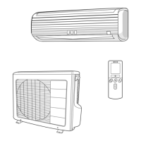
ROOM AIR CONDITIONER
INDOOR UNIT + OUTDOOR UNIT
MAY 2003
Refrigeration & Air-Conditioning Division
SERVICE MANUAL
PM
REFER TO THE FOUNDATION MANUAL
TECHNICAL INFORMATION
FOR SERVICE PERSONNEL ONLY
(W)
(A)
(kW)
(B.T.U./h)
(W)
(A)
(kW)
(B.T.U./h)
W
H
D
(kg)
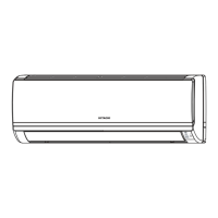
RAK-25NH4 RAC-25NH4
DC INVERTER (WALL TYPE)
TYPE
MODEL
POWER SOURCE
TOTAL INPUT
TOTAL AMPERES
CAPACITY
TOTAL INPUT
TOTAL AMPERES
CAPACITY
DIMENSIONS
(mm)
NET WEIGHT
SPECIFICATIONS
860
285
183
9.0
RAK-25NH4
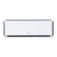
RAK-35NH4
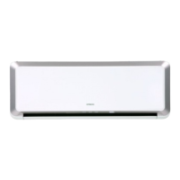
RAK-50NH4
CONTENTS
SPECIFICATIONS ------------------------------------------------------------------- 5
HOW TO USE ------------------------------------------------------------------------ 6
CONSTRUCTION AND DIMENSIONAL DIAGRAM --------------------- 29
MAIN PARTS COMPONENT--------------------------------------------------- 31
WIRING DIAGRAM ---------------------------------------------------------------- 33
CIRCUIT DIAGRAM --------------------------------------------------------------- 35
PRINTED WIRING BOARD LOCATION DIAGRAM --------------------- 41
BLOCK DIAGRAM ----------------------------------------------------------------- 43
BASIC MODE ----------------------------------------------------------------------- 45
REFRIGERATING CYCLE DIAGRAM --------------------------------------- 59
AUTO SWING FUNCTION------------------------------------------------------ 61
DESCRIPTION OF MAIN CIRCUIT OPERATION ----------------------- 62
SERVICE CALL Q & A ---------------------------------------------------------- 93
TROUBLE SHOOTING ----------------------------------------------------------- 96
PARTS LIST AND DIAGRAM ------------------------------------------------- 116
RAK-25NH4/RAC-25NH4
RAK-35NH4/RAC-35NH4
RAK-50NH4/RAC-50NH4
RAC-25NH4
RAC-35NH4
RAC-50NH4
COOLING
HEATING
INDOOR UNIT
OUTDOOR UNIT
INDOOR UNIT
OUTDOOR UNIT
1 PHASE, 50 Hz, 220-230V
695 (155~1,050)
3.20-3.05
2.50 (0.90 ~ 3.00)
8,540
900 (115 ~ 1,400)
4.15-4.00
3.50 (0.90 ~ 5.00)
11,950
750
570
280
38
860
285
183
9.0
750
570
280
38
1 PHASE, 50 Hz, 220-230V
1,080 (155~1,280)
4.94-4.72
3.50 (0.90 ~ 4.00)
11,950
1,320 (115 ~ 1,920)
6.04-5.77
4.80 (0.90 ~ 6.60)
16,390
After installation
OUTDOOR UNIT
INDOOR UNIT
860
285
183
9.0
850
650
298
60
1 PHASE, 50 Hz, 220-230V
1,780 (155~2,200)
8.17-7.82
5.00 (0.90 ~ 5.20)
17,070
1,970 (115 ~ 2,100)
9.04-8.65
6.50 (0.90 ~ 8.10)
22,200
RAK-35NH4 RAC-35NH4
RAK-50NH4 RAC-50NH4
NO. 0174E(R)