EasyManua.ls Logo

Hitachi RAK-50PPB User Manual

Hitachi RAK-50PPB
148 pages
To Next Page IconTo Next Page
Page #1 background imageLoading...
Page #1 background image
SPECIFICATIONS AND PARTS ARE SUBJECT TO CHANGE FOR IMPROVEMENT
ROOM AIR CONDITIONER
INDOOR UNIT + OUTDOOR UNIT
SERVICE MANUAL
REFER TO THE FOUNDATION MANUAL
TECHNICAL INFORMATION
FOR SERVICE PERSONNEL ONLY
SPECIFICATIONS
CONTENTS
SPECIFICATIONS ------------------------------------------------------------------- 6
HOW TO USE ----------------------------------------------------------------------10
CONSTRUCTION AND DIMENSIONAL DIAGRAM --------------------- 43
MAIN PARTS COMPONENT --------------------------------------------------- 48
WIRING DIAGRAM ---------------------------------------------------------------- 50
CIRCUIT DIAGRAM --------------------------------------------------------------- 52
After installation
BLOCK DIAGRAM ----------------------------------------------------------------- 55
BASIC MODE ----------------------------------------------------------------------- 56
REFRIGERATING CYCLE DIAGRAM --------------------------------------- 67
DESCRIPTION OF MAIN CIRCUIT OPERATION ----------------------- 73
SERVICE CALL Q & A ---------------------------------------------------------- 98
TROUBLE SHOOTING -----------------------------------------------------------102
PARTS LIST AND DIAGRAM --------------------------------------------------1
HHAW
RAK-18PPB/RAC-18WPB
RAK-25PPB/RAC-25WPB
RAK-35PPB/RAC-35WPB
RAK-50PPB/RAC-50WPB
INDOOR UNITOUTDOOR UNIT
INDOOR UNIT
OUTDOOR UNIT
INDOOR UNIT OUTDOOR UNIT INDOOR UNIT OUTDOOR UNIT
INDOOR UNIT OUTDOOR UNIT
RAK-18P
RAC-18W
RAK-25P RAC-25W RAK-35P RAC-35W
RAK-50P RAC-50W
(KW)
(B.T.U./h)
(KW)
(B.T.U./h)
W
780 660(+60) 780 660(+60) 900 750(+65)
900 792(+91)
H
280 530 280 530 295 548
295 600
D
218 278(+35) 218 278(+35) 230
288(+27.5)
230 299(+47)
MODEL
POWER SOURCE
TOTAL INPUT (W
TOTAL AMPERES (A)
CAPACITY
COOLING
HEATING
TOTAL INPUT (W
TOTAL AMPERES (A)
CAPACITY
1,090 (250
1,460)
DIMENSIONS
(mm)
1,560 (500
2,100)
3.12-2.97
2.00 (0.90
2.50)
8,530 (3,070
10,580)
580 (250
970)
2.50 (0.90
27.57.5 27.57.5 3410
10
3.20)
3.49-3.34
11,600 (3,070
15,010)
880 (250
1,250)
NET WEIGHT (Kg)
TYPE
DC INVERTER
1 PHASE,50HZ,220-230V
1 PHASE,50HZ,220-230V 1 PHASE,50HZ,220-230V
550 (
700 (250
) 010 , 1
1,290)
4.56-4.36
3.40 (0.90
4.40)
11,600 (3,070
15,010)
4.87-4.66
1,100 (250
1,700)
5.51-5.27
14,330 (3,070
17,060)
3.75-3.59
2.50 (0.90
3.10)
8,530 (3,070
10,580)
7.30-6.98
3.50 (0.90
4.00)
5.00 (1.90
5.20)
11,940 (3,070
13,650)
17,060 (6,480
17,740)
20,470 (7,510
24,910)
7.93-7.59
1,660 (500
2,750)
4.20 (0.90
5.00)
6.00 (2.20
7.30)
25
0
Hitachi Household Appliances(Wuhu) Co., Ltd.
PB
PB
PB PB PB PB
PB PB
RAC-18WPB
RAC-25WPB
RAK-18PPB
RAK-25PPB
RAC-50WPB
RAC-35WPB
1 PHASE,50HZ,220-230V
RAK-35PPB
RAK-50PPB
NO.0080E-3
38
40
PROCEDURE FOR DISASSEMBLY AND REASSEMBLY-------------70
RAR-5E2
RAR-5E1

Table of Contents

Other manuals for Hitachi RAK-50PPB

Question and Answer IconNeed help?

Do you have a question about the Hitachi RAK-50PPB and is the answer not in the manual?

Hitachi RAK-50PPB Specifications

General IconGeneral
TypeSplit System
Cooling Capacity5.0 kW
RefrigerantR410A
Power Supply220-240V, 50Hz
Indoor Unit Weight9.5 kg

Summary

Hitachi Service Manual Technical Information

Safety During Repair Work

Working Standards for Semiconductor Protection

Specifications

Remote Controller Manual

Preparation Before Operation

Instructions for installing batteries and fixing the remote controller holder.

Remote Controller Names and Functions

Display

Indicates room temp, timer status, function, and airflow rate.

Room Temperature Setting Buttons

Buttons to adjust the desired room temperature setting.

START/STOP Button

Button to start or stop the air conditioner operation.

Fan Speed Selector Button

Button to determine and adjust the fan speed.

ECO Button

Button to set the energy-saving ECO mode.

Various Remote Controller Functions

Auto Restart Control

Details how the unit restarts automatically after a power failure.

Heating Operation

Defrosting Process

Explains the defrosting procedure and its indicators during heating.

Dehumidifying Operation

Dehumidifying Function Details

Describes how dehumidifying works based on room temperature.

Cooling Operation

Fan Operation

Auto Swing Operation

Powerful Operation Mode

Silent Operation Mode

ECO Operation Mode

Leave Home Operation

Clean Operation

Once Timer (On/Off Timer) Operation

ECO Sleep Timer Operation

Weekly Timer Operation

Weekly Timer Setting Modes

Procedure to select or deactivate Mode A or Mode B for weekly timer.

Setting Non-Active Weekly Timer

Instructions to deactivate the weekly timer function.

Weekly Timer Data Copy and Paste

Method for copying and pasting reservation schedules between days.

Weekly Timer Data Deletion

Procedure to delete one program number or an entire day's reservation.

Info Function

Info Function: Temperature Check

Checking remote controller temperature and retrieving indoor unit calendar/clock.

Info Function: Monthly Power Consumption

Displaying monthly power consumption for heating and cooling operations.

Operation Mode Lock Setting

Safety Precautions

Names and Functions of Parts

Indoor Unit Parts

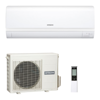
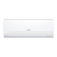
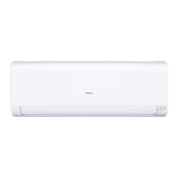
Identifies and describes components of the indoor unit.

Outdoor Unit Parts

Identifies and describes components of the outdoor unit.

Indoor Unit Indicators

Explains the meaning of the Timer Lamp and Operation Lamp.

Maintenance Procedures

Air Filter Maintenance

Procedure for cleaning the air filter to maintain efficiency and airflow.

Front Panel Cleaning

Steps for cleaning the front panel of the indoor unit.

Maintenance for Long Off Periods

Procedure to prepare the unit for extended periods of non-operation.

Operational Information

Unit Capabilities

Details heating, cooling, and dehumidifying capabilities and limitations.

Regular Inspection Points

Checklist for periodic inspection to ensure safety and proper function.

After Sales Service and Warranty

Guidance on what to check before requesting service.

Construction and Dimensional Diagrams

Indoor Unit Diagrams

Dimensional drawings and construction details for the indoor unit.

Outdoor Unit Diagrams

Dimensional drawings and construction details for the outdoor unit.

Main Parts Components

Thermostat Specifications

Specifications for the room temperature thermostat and IC operation modes.

Fan Motor Specifications

Specifications for the indoor and outdoor fan motors.

Outdoor Unit Main Electric Components

Details on major electrical components for the outdoor unit, like reactors.

Compressor Motor Specifications

Wiring Diagrams

Printed Wiring Board Wiring Diagram

Circuit Diagram

Block Diagram

Basic Mode Operation

Refrigerating Cycle Diagram

Disassembly and Reassembly Procedures

Indoor Unit Disassembly and Reassembly

Step-by-step guide for taking apart and reassembling the indoor unit.

Tangential Fan and Motor Disassembly

Instructions for removing and disassembling the tangential fan and motor.

Outdoor Unit Electrical Parts Removal

Procedure for removing electrical parts from the outdoor unit.

Main Circuit Operation Description

Control Power Circuit Operation

Explanation of the control power circuit's function and components.

Reset Circuit Operation

Indoor Fan Motor Drive Circuit

Buzzer Circuit Operation

Remote Control Reception Circuit

Initial Setting Circuit Operation

Temporary Switch Circuit Operation

Room Temperature Thermistor Circuit

Heat Exchanger Thermistor Circuit

Dip-Switch Settings

Indoor/Outdoor Communication Circuits

Stepping Motor Drive Circuit

Power Circuit Operation

Low Voltage Power Circuit

P.W.B. for Power Circuit

Reversing Valve Control Circuit

Temperature Detection Circuit

Electric Expansion Valve Circuit

Outdoor DC Fan Motor Control Circuit

Fan Motor Checking Procedure

Power Circuit Operation (RAC-50WPB)

Service Call Q & A

Common Q&A

General questions and answers regarding common operational issues.

Wireless Remote Control Q&A

Questions and answers specific to remote control operation and troubleshooting.

Troubleshooting

Troubleshooting Inspection Instructions

Important safety and procedural notes before starting troubleshooting.

Power Circuit Discharge and Shut Off Procedure

Indoor Unit Electric Parts Structure

Removing Indoor Unit Electrical Parts

Step-by-step guide for removing electrical components from the indoor unit.

Removing Control P.W.B.

Instructions for removing the control printed wiring board.

Removing Indicating P.W.B.

Instructions for removing the indicating printed wiring board.

Other Component Handling Instructions

Connector and Receptacle Handling

Guidelines for safely detaching and reattaching connectors and receptacles.

Troubleshooting Support

Self-Diagnosis Display (Indoor Unit)

Details on self-diagnosis display for failures detected on the indoor unit.

Self-Diagnosis Display (Outdoor Unit)

Details on self-diagnosis display for failures detected on the outdoor unit.

Self-Diagnosis Memory Function

Explanation of storing and retrieving failure modes from memory.

Self-Diagnosis Lighting Mode

Forced Cooling Operation

Diagnosis and Troubleshooting Flow

Checking Indoor Unit Electrical Parts

Troubleshooting: No Power

Troubleshooting: No Remote Signal

Identifying Remote Signal Jamming Sources

Diagnostic steps to identify external interference affecting remote signals.

Jamming: Lighting Equipment Effects

Jamming: Other Equipment Interference

Jamming: Electrical Products & Grounding

Jamming: Radio Waves & Sunlight

Troubleshooting: Compressor Not Running

Troubleshooting: Fan Motor Not Stopping

Troubleshooting: Timer Lamp Blinking Codes (1-4)

Troubleshooting: Timer Lamp Blinking Code (9)

Troubleshooting: Timer Lamp Blinking Code (10)

Troubleshooting: Timer Lamp Blinking Code (12)

Troubleshooting: Timer Lamp Blinking Code (13)

Checking Outdoor Unit Electrical Parts

Troubleshooting: LD301 Blinking Codes (13, 9, 1, Stop)

Troubleshooting: LD301 Blinking Codes (10, 7, 6, 16)

Troubleshooting: LD301 Blinking Codes (4, 3, 2)

Troubleshooting: LD301 Blinking Codes (12, 11)

How to Change Shift Value Temperature

Preventing Remote Controller Interference

Operation Mode Lock Setting

Display Operation Mode Setting

Checking the Refrigerating Cycle

Outdoor Unit Test Switch Operation

Operating Outdoor Unit Independently

Parts List and Diagram (Indoor Unit)

Parts List and Diagram (Outdoor Unit)

Related product manuals