EasyManua.ls Logo

Hitachi RAS-18YH6 User Manual

Hitachi RAS-18YH6
95 pages
To Next Page IconTo Next Page
Page #1 background imageLoading...
Page #1 background image
NO. 0019E
SPECIFICATIONS AND PARTS ARE SUBJECT TO CHANGE FOR IMPROVEMENT
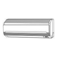
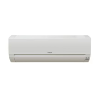
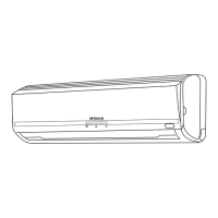
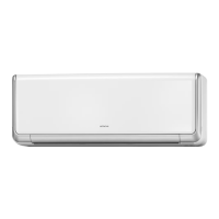
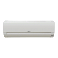
ROOM AIR CONDITIONER
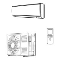
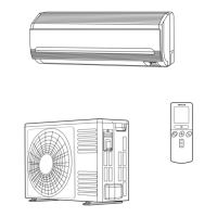
INDOOR UNIT + OUTDOOR UNIT
DECEMBER 2006 Hitachi Household Appliances(Wuhu) Co.,Ltd.
SERVICE MANUAL
AW
REFER TO THE FOUNDATION MANUAL
TECHNICAL INFORMATION
FOR SERVICE PERSONNEL ONLY
(W)
(A)
(kW)
(B.T.U./h)
(W)
(A)
(kW)
(B.T.U./h)
W
H
D
(kg)
RAS-18YH6 RAC-18YH6
DC INVERTER (WALL TYPE)
TYPE
MODEL
POWER SOURCE
TOTAL INPUT
TOTAL AMPERES
CAPACITY
TOTAL INPUT
TOTAL AMPERES
CAPACITY
DIMENSIONS
(mm)
NET WEIGHT
SPECIFICATIONS
780
280
210
9.5
RAS-18YH6
RAS-25YH6
CONTENTS
SPECIFICATIONS ------------------------------------------------------------------- 4
HOW TO USE ----------------------------------------------------------------------- 5
CONSTRUCTION AND DIMENSIONAL DIAGRAM --------------------- 15
MAIN PARTS COMPONENT --------------------------------------------------- 17
WIRING DIAGRAM ---------------------------------------------------------------- 19
CIRCUIT DIAGRAM --------------------------------------------------------------- 20
RAS-18YH6/RAC-18YH6
RAS-25YH6/RAC-25YH6
RAC-18YH6
RAC-25YH6
COOLING
HEATING
INDOOR UNIT
OUTDOOR UNIT
INDOOR UNIT
OUTDOOR UNIT
1 PHASE, 50 Hz, 220-230V
550 (155 ~ 1,010)
2.95-2.81
2.00 (0.90 ~ 2.50)
6,820 (3,070 ~ 8,530)
580 (115 ~ 970)
2.93-2.81
2.50 (0.90 ~ 3.20)
8,530 (3,070 ~ 10,920)
505
27
780
280
210
9.5
505
27
1 PHASE, 50 Hz, 220-230V
700 (155 ~ 1,290)
3.75-3.59
2.50 (0.90 ~ 3.10)
8,530 (3,070 ~ 10,580)
880 (115 ~ 1,250)
4.45-4.26
3.40 (0.90 ~ 4.40)
11,600 (3,070 ~ 15,010)
After installation
RAS-25YH6 RAC-25YH6
BLOCK DIAGRAM ----------------------------------------------------------------- 22
BASIC MODE ----------------------------------------------------------------------- 23
REFRIGERATING CYCLE DIAGRAM --------------------------------------- 29
DESCRIPTION OF MAIN CIRCUIT OPERATION ----------------------- 30
SERVICE CALL Q & A ---------------------------------------------------------- 60
TROUBLE SHOOTING ----------------------------------------------------------- 63
PROCEDURE FOR DISASSEMBLY AND REASSEMBLY ------------ 87
PARTS LIST AND DIAGRAM -------------------------------------------------- 89
700 (+68) 700 (+68)
258 (+48) 258 (+48)
Question and Answer IconNeed help?

Do you have a question about the Hitachi RAS-18YH6 and is the answer not in the manual?

Hitachi RAS-18YH6 Specifications

General IconGeneral
BrandHitachi
ModelRAS-18YH6
CategoryAir Conditioner
LanguageEnglish

Summary

Safety During Repair Work

Working Standards for Preventing Breakage of Semiconductors

Caution

How to Use

Safety Precaution

General safety advice and warnings for operating the unit safely.

Precautions During Installation

Specific safety measures to follow during the installation process.

Precautions During Operation

Safety guidelines to observe while the air conditioner is running.

Precautions During Shifting or Maintenance

Safety recommendations for moving or maintaining the unit.

How to Set the Timer

Regular Inspection

After Sales Service and Warranty

When Asking for Service, Check the Following Points.

Specific checks to perform before contacting customer service for troubleshooting.

Wiring Diagram

Block Diagram

Basic Mode

Refrigerating Cycle Diagram

Description of Main Circuit Operation

1. Reset Circuit

How the reset circuit initializes the microcomputer program upon power on/off.

3. Intelligent Power Module Circuit (IPM Circuit)

6. Peripheral Circuits of Microcomputer

6-1. Peak Current Cutoff Circuit

How the circuit detects and stops overcurrent to protect components.

6-2. Overload Control Circuit (OVL Control Circuit)

Mechanism to reduce compressor speed and load to prevent overload.

6-3. Reset Circuit

How the reset circuit initializes the microcomputer on power changes.

6-4. Temperature Detection Circuit

Circuits that detect overheat, defrost, and outdoor temperatures.

6-5. Reversing Valve Control Circuit

Control of the reversing valve based on operation mode for heating/cooling.

Trouble Shooting

Service Call Q & A

Troubleshooting When Timer Lamp Blinks.

Self-Diagnosis Lighting Mode

Precautions for Checking

Discharge, Procedure and Power Shut Off Method for Power Circuit

Structure of an Indoor Unit Electric Parts

Other Cautions

The Support Function of Failure Diagnosis

Checking the Indoor/Outdoor Unit Electrical Parts and Refrigerating

Checking the Indoor Unit Electrical Parts

Checking the Remote Controller

Checking Outdoor Unit Electrical Parts

Checking the Refrigerating Cycle

How to Operate Using the Service Switch the Outdoor Unit

How to Operate the Outdoor Unit Independently

IPM (Intelligent Power Module) Diagnosis

Diagnosis Procedure for Power Module Using Multimeter

Step-by-step guide for testing the IPM using a multimeter for continuity and swing status.

Procedure for Disassembly and Reassembly

Related product manuals