FIXTURE SCREW
FIXTURE SCREW
ON
OFF
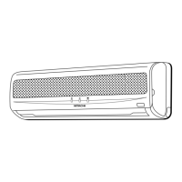
MODEL RAS-E10H2
ELEC. COVER
P.W.B. SUPPORTER
P.W.B. SUPPORTER
P.W.B. SUPPORTER
P.W.B. SUPPORTER
CN2
CN3
CN8
INDICATING P.W.B.
HOOK
INDICATING P.W.B.
HOLDER
ICP2
ICP1
12V
Power circuit
12V line
5V line
ZD121
20V
Zener Diode
0V
5V
Power circuit
M
35V line
ICP1
OK
Q111
S
D
G
IC11
1
0V
OK
Lock
Press her
e
Unlock
Forbidden area (Gate (G) to 0 V)
35 V line
S: Source
D: Drai
n
G: Gat
e
Forbidden
area
Indoor unit fan motor
(1) Cautions concerning ICP (IC Pr
t circuit will open the ICP immediately
t circuit will open the ICP immediately.t circuit will open the ICP immediately
e the cause of this phenomenon and replace the IC
If the remedy is improper
, the ICP may open again., the ICP ma
circuit, causing the ICP1
(2) The CN3 (power supply) and CN10 (fan motor) are the connectors with lock mechanism.
Press the lock with your fingers to unlock and remove the connector.
(3) When checking the voltage and waveform, do not connect the probes to the forbidden areas show
below. Touching them may cause the ICP1 blowout and Q111 failure.
Failure to do so may cause overcurrent to the fan motor and P.W.B.s (micro computer, IC and the
or insert the CN10, be sure to shut off the power
is contacted with the gate G , the Q111 may have the continuous ON state to supply overcurrent in the
When checking the switching waveform of the Q111, set the source S to the base and measure the