EasyManua.ls Logo

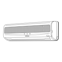
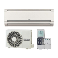
Hitachi RAS-E10H2 - User Manual

Hitachi RAS-E10H2
96 pages
To Next Page IconTo Next Page
Loading...
AW NO. 0015E
SERVICE MANUAL
TECHNICAL INFORMATION
REFER TO THE FOUNDATION MANUAL
ROOM AIR CONDITIONER
INDOOR UNIT + OUTDOOR UNIT
SPECIFICATIONS AND PARTS ARE SUBJECT TO CHANGE FOR IMPROVEMENT
Printed in Japan (TSK)
FOR SERVICE PERSONNEL ONLY
SPECIFICATIONS
SPECIFICATIONS ‥‥‥‥‥‥‥‥‥‥‥‥‥‥‥4
HOW TO USE ‥‥‥‥‥‥‥‥‥‥‥‥‥‥‥‥5
CONSTRUCTION AND DIMENSIONAL DIAGRAM
‥‥15
MAIN PARTS COMPONENT ‥‥‥‥‥‥‥‥‥‥17
WIRING DIAGRAM ‥‥‥‥‥‥‥‥‥‥‥‥‥‥19
WIRING DIAGRAM OF THE PRINTED WIRING BOARD
‥20
BLOCK DIAGRAM‥‥‥‥‥‥‥‥‥‥‥‥‥‥‥25
BASIC MODE‥‥‥‥‥‥‥‥‥‥‥‥‥‥‥‥‥27
REFRIGERATING CYCLE DIAGRAM ‥‥‥‥‥‥36
DESCRIPTION OF MAIN CIRCUIT OPERATION
‥‥‥37
SERVICE CALL Q & A ‥‥‥‥‥‥‥‥‥‥‥‥67
TROUBLE SHOOTING  ‥‥‥‥‥‥‥‥‥‥‥‥70
PROCEDURE FOR DISASSEMBLY AND REASSEMBLY
‥‥94
PARTS LIST AND DIAGRAM ‥‥‥‥‥‥‥‥‥96
CONTENTS
AW NO. 0015E
RAS-E10H2 / RAC-E10H2
RAS-E10H2 /
RAC-E10H2
RAS-E10H2
RAC-E10H2
(W)
(A)
(kW)
(B.T.U./h)
(W)
(A)
(kW)
(B.T.U./h)
W
H
D
(kg)
DC INVERTER (WALL TYPE)
TYPE
MODEL
POWER SOURCE
TOTAL INPUT
TOTAL AMPERES
CAPACITY
TOTAL INPUT
TOTAL AMPERES
CAPACITY
DIMENSIONS
(mm)
NET WEIGHT
COOLING
HEATING
RAS-E10H2 RAC-E10H2
780
280
210
9.5
INDOOR UNIT OUTDOOR UNIT
1 PHASE, 50Hz, 220-230V
700 (155 - 1,290)
3.75 - 3.59
2.50 (0.90 - 3.10)
8,530 (3,070 - 10,580)
880 (115 - 1,250)
4.45 - 4.26
3.40 (0.90 - 4.40)
11,600 (3,070 - 15,010)
700(+68)
※
(+48)
※
505
258
27
After installation
※
FEBRUARY
2006
Hitachi Household Appliances (Wuhu) Co.,Ltd.
Question and Answer IconNeed help?

Do you have a question about the Hitachi RAS-E10H2 and is the answer not in the manual?

Hitachi RAS-E10H2 Specifications

General IconGeneral
BrandHitachi
ModelRAS-E10H2
CategoryAir Conditioner
LanguageEnglish

Summary

Safety During Repair Work

Working Standards for Semiconductor Handling

Operational Cautions

How to Use the Air Conditioner

Timer Setting Procedures

Step-by-step instructions for setting various timer functions.

Routine Maintenance Procedures

Guidelines for regular cleaning and upkeep of the air conditioner.

Part Identification and Dimensions

Remote Controller Operation

Specific Operation Modes

Heating Operation Guide

Instructions and conditions for effective heating operation.

Dehumidifying Operation Guide

Instructions and conditions for effective dehumidifying operation.

Cooling and Fan Operations

Cooling Operation Guide

Instructions and conditions for effective cooling operation.

Fan Operation Guide

How to use the unit as a fan for air circulation.

HOW TO SET THE TIMER

ADVANCED OPERATION FEATURES

ROUTINE MAINTENANCE PROCEDURES

UNIT INFORMATION, INSPECTION AND SERVICE

MAIN COMPONENT SPECIFICATIONS

COMPRESSOR MOTOR SPECIFICATIONS

WIRING DIAGRAMS

PRINTED WIRING BOARD DIAGRAM

SYSTEM BLOCK DIAGRAM

BASIC OPERATION MODES OVERVIEW

MODE DATA FILE PARAMETERS

BASIC COOLING OPERATION DETAILS

BASIC HEATING OPERATION DETAILS

REFRIGERATION CYCLE AND DEFROSTING PROCESSES

REFRIGERATING CYCLE DIAGRAM

MAIN CIRCUIT OPERATION DESCRIPTIONS

Reset Circuit Operation

How the reset circuit initializes the microcomputer program on power cycle.

Receiver Circuit Operation

How the receiver circuit processes signals from the remote controller.

Buzzer Circuit Operation

Explanation of the buzzer circuit's sound generation mechanism.

Auto Sweep Motor Circuit Operation

How the auto sweep motor controls air deflector movement.

Initial Setting Circuit Operation

How the microcomputer sets initial values upon power supply.

Power Supply Circuit Operation

How power is supplied to various unit components.

Fan Motor Drive Circuit Operation

How the fan motor speed is controlled.

Power Circuit Operation (Main PWB)

Details on the power circuit converting AC to DC for various functions.

Indoor;Outdoor Interface Circuit

How indoor and outdoor units communicate via an interface circuit.

IPM Circuit Operation

Operation of the Intelligent Power Module circuit.

Drive Circuit Operation

Details on the drive circuits for unit components.

Power Circuit for Printed Wiring Board

Specific power circuit details for the printed wiring board.

Peripheral Circuits of Microcomputer

Circuits connected to the microcomputer for its operation.

Peak Current Cutoff Circuit

Circuit that protects against excessive peak currents.

Overload Control Circuit Operation

Circuit that manages overload conditions to protect components.

Reset Circuit Details

Detailed explanation of the reset circuit's operation.

Temperature Detection Circuit Details

Detailed explanation of temperature detection circuits.

Reversing Valve Control Circuit Details

Detailed explanation of the reversing valve control circuit.

Electric Expansion Valve Control Circuit Details

Detailed explanation of the electric expansion valve control circuit.

Outdoor DC Fan Motor Control Circuit Details

Detailed explanation of the outdoor DC fan motor control circuit.

Peak Current Cutoff Circuit Details

Detailed description of the peak current cutoff circuit.

Overload Control Circuit Details

Detailed description of the overload control circuit.

Reset Circuit Details

Detailed explanation of the reset circuit's operation.

Temperature Detection Circuit Details

Detailed explanation of temperature detection circuits.

Reversing Valve Control Circuit Details

Detailed explanation of the reversing valve control circuit.

Electric Expansion Valve Control Circuit Details

Detailed explanation of the electric expansion valve control circuit.

Outdoor DC Fan Motor Control Circuit Details

Detailed explanation of the outdoor DC fan motor control circuit.

SERVICE CALL Q&A

TROUBLESHOOTING GUIDE

Precautions for Checking

Important safety precautions before performing checks.

POWER CIRCUIT DISCHARGE AND SHUT OFF PROCEDURE

INDOOR UNIT ELECTRIC PARTS DISASSEMBLY

FAILURE DIAGNOSIS SUPPORT FUNCTIONS

TROUBLESHOOTING TIMER LAMP BLINKS

Self-Diagnosis Lighting Mode Interpretation

Interpreting blinking patterns of the timer lamp for fault diagnosis.

ELECTRICAL PARTS AND REFRIGERATING SYSTEM CHECK

CHECKING INDOOR UNIT ELECTRICAL PARTS

Indoor Fan Operation Check

Troubleshooting steps if the indoor fan does not operate.

Air Deflector Movement Check

Troubleshooting steps if the air deflector does not move.

Control PWB Power Circuit Check

Checking the power circuit of the control Printed Wiring Board.

REMOTE CONTROLLER FUNCTION CHECK

CHECKING OUTDOOR UNIT ELECTRICAL PARTS

REFRIGERATING CYCLE DIAGNOSTIC CHECK

OUTDOOR UNIT SPECIAL OPERATION MODES

Operating Outdoor Unit via Service Switch

How to operate the outdoor unit using the service switch.

Independent Outdoor Unit Operation

Procedure for operating the outdoor unit independently.

IPM (INTELLIGENT POWER MODULE) DIAGNOSIS

POWER MODULE DIAGNOSIS WITH MULTIMETER

DISASSEMBLY AND REASSEMBLY PROCEDURES (INDOOR UNIT)

Front Panel Removal Procedure

Steps for removing the front panel of the indoor unit.

Front Cover Removal Procedure

Steps for removing the front cover of the indoor unit.

Control and Indicating PWB Removal

Procedure for removing the control and indicating PWB.

DISASSEMBLY AND REASSEMBLY PROCEDURES (CONTINUED)

Tangential Air Flow Fan and Motor Removal

Steps for removing the fan and fan motor assembly.

Outdoor Unit Electrical Parts Removal

Steps for removing electrical parts from the outdoor unit.

PARTS LIST AND DIAGRAM (INDOOR UNIT)

PARTS LIST AND DIAGRAM (OUTDOOR UNIT)

Related product manuals