FOR SERVICE PERSONNEL ONLY
SAFETY PRECAUTION
• Read the safety precautions carefully before operating the unit.
• The contents of this section are vital to ensure safety. Please pay special attention to the following sign.
WARNING .......... Incorrect methods of installation may cause death or serious injury.
CAUTION .......... Improper installation may result in serious consequence.
Make sure to connect earth line.
This sign in the figures indicates prohibition.
Be sure that the unit operates in proper condition after installation. Explain to customer the proper operation and maintenance of
the unit as described in the user' s guide. Ask a customer to keep this installation manual together with the instruction manual.
TINU ROODNI
WARNING
THE CHOICE OF MOUNTING SITE (Please note the following matters and obtain permission from customer before installation.)
• The unit should be mounted at stable, non-vibratory location
which can provide full support to the unit.
CAUTION
• No nearby heat source and no obstruction near the air
outlet is allowed.
• The clearance distances from top, right and left are
specified in figure below.
• The location must be convenient for water drainage and
pipe connection with the Outdoor unit.
• To avoid interference from noise, please place the unit and
its remote controller at least 1m from the radio and
television.
• To avoid any error in signal transmission from the remote
controller, please put the controller far away from high-
frequency machines and high-power wireless systems.
TINU ROODTUO
WARNING
• The Outdoor unit must be mounted at a location which can
support heavy weight. Otherwise, noise and vibration will
increase.
CAUTION
• Do not expose the unit under direct sunshine or rain.
Besides, ventilation must be good and clear of obstruction.
• The air blown out of the unit should not point directly to
animals or plants.
• The clearances of the unit from top, left, right and front are
specified in figure below. At least three of the above sides
must be open air.
• The installation height should be at least 2,300 mm or more
from the floor.
• Be sure that the hot air blown out of the unit and noise do
not disturb the neighbourhood.
• Do not install at a location where there is flammable gas,
steam, oil and smoke.
• The location must be convenient for water drainage.
• Place the Outdoor unit and its connecting cord at least 1 m
away from the antenna or signal line of television, radio or
telephone. This is to avoid noise interference.
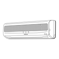
Names of Indoor Components
Direction of Piping
Backward piping
from left
Connection
There are 6 directions allowed,
namely, backward piping,
backward piping from left,
horizontally piping from right,
horizontally piping from left,
vertically down from right, vertically
down from left.
Figure showing the Installation
of Indoor and Outdoor Unit.
above
50mm
above 50mm
above 50mm
mm003 tuoba
m54.0 tuoba
dneb ton tsum
The indoor piping should be
insulated with the enclosed
insulation pipe. (If the insulator is
insufficient, please use commercial
products.)
• The refrigerating machine oil is
easily affected by moisture. Use
caution to prevent water from
entering the cycle.
• The difference in height between
the indoor and outdoor unit
should be kept below 10m.
• The connecting pipe, no matter
big or small, should all be
insulated with insulation pipe and
then wrapped with vinyl tape.
(The insulator will deteriorate if
it is not wrapped with tape).
The connection of insulated drain
hose.
Inner diameter 16mm
Please use insulated drain hose for
the indoor piping (commercial
product)
Be sure to
completely
seal any gap
with putty.
TINU ROODNI
1 Installation of Hanger, Wall Penetration and Installation of Protection Pipe
CAUTION
• The draining of the water container inside the Indoor unit can be done from the left.
Therefore the hanger must be fixed horizontally or slightly tilted towards the side of
drain hose. Otherwise, condensed water may overflow the water container.
Direct Mounting On The Wall
• Please use hidden beams in the wall to hold the hanger.
Procedures of Installation and Precautions
• Procedures to fix the hanger.
Wall Penetration and Installation of Protection Pipe
• Drill a ø65mm hole on wall which is
slightly tilted towards the outdoor side.
Drill the wall at a small angle.
• Cut the protection pipe according to the
wall thickness.
• Empty gap in the sleeve of protection
pipe should be completely sealed with
putty to avoid dripping of rain water into
the room.
• Please ensure smooth flow of water
when installing the drain hose. Improper
installing may wet your funiture.
• An IEC approved power cord should be
used. Power cord type: NYM.
WARNING
Be sure that the wire is not
in contact with any metal in
the wall. Please use the
protection pipe as wire
passing through the hollow
part of the wall so as to
prevent the possibility of
damaged by mouse.
Unless it seals completely,
any air with high humidity
flows from outdoor and any
dew may drop.
Seal with
putty
Protection
pipe
Sleeve of
protection
pipe
Seal with
putty
Outdoor
Indoor
2-5mm
2 Installation Of The Indoor Unit
WALL
When the power is
supplied from the
indoor unit, pull the
power cable from the
cable drawer at the
right or left side of
the indoor unit.
Screw the hanger at the
positions possibly near the
upper and lower hooks where
the indoor unit is hung. Use 4 or
more screws to fix the hanger.
1
PIPING FROM THE RIGHT SIDE (BACKWARD, DOWNWARD, HORIZONTAL)
Preparation
• Connect connecting cord.
• Pull out the pipe, connecting cord and drain hose.
Installation
• Insert the pipe through the wall hole.
1 The upper part of the Indoor unit is hanged on the
hanger.
2 The projection at the lower part of the Indoor unit is
hooked onto the hanger.
Connecting cords, pipe and
drain hose must be laid
together with Vinyl tape.
Lift the body
of the unit
upwards and
then force it
downwards.
1 Hanger
Refrigerating
Pipe
Protection
Pipe
Drain Hose
Connecting Cord
Projection
2
PIPING FROM THE LEFT SIDE (BACKWARD, DOWNWARD, HORIZONTAL)
Preparation
Changed of Drain Hose and Installation Procedures.
•
Exchange the location of drain hose and drain cap while installing the pipe from the left side as
shown in below. Be sure to plug in the drain hose until the insulating material folds upon itself.
• Please use pliers to pull out the drain cap.
(This is an easier way to remove the drain
cap).
CAUTION
Insufficient insert may
result in water leakage.
Drain Hose
Drain cap
•
Remove low cover
•
Insert drain cap up to the
location securely till the
cap stops.
Cutting Low Cover bush
• While installing the pipe from the right, left or
bottom side, use a knife to cut openings as
shown in figure. Then smoothen the edges of
openings with a file.
Openings
•
Push the pipe deeply until the insulating
section of the drain hose end gets over the
rib at the indoor unit side.
Openings
CAUTION
• The rubber strap used for fixing the insulator
should not be tied with great force. Otherwise,
this will damage heat insulation and causes
water condensation.
• Please pull the lower part of the Indoor unit
outwards to check if the unit is hooked onto
the hanger. Improper installation may cause
vibration and noise.
• Transform the piping while holding down the
lower portion of pipe-support by hand.
Pipe
Rubber strap tied
with great force
INSTALLATION AFTER CONNECTION OF REFRIGERATING PIPES
• The refrigerating pipe should be adjusted to fit into
the hole on the wall and then ready for further
connection.
• The terminals of 2 connected pipes must be covered
with insulator used for terminal connection. Then the
pipes are wrapped with insulation pipe.
• Connect the connecting cord after removing low
cover.
(Refer to "CONNECTION OF POWER CORD")
• After adjustment, fit the connecting cord and pipes
into the space available under the unit. Use holder to
hold them tight.
• Holder can be attached at the either of 2 places.
Please select the easier position.
THE CONNECTION OF REFRIGERATING PIPE DURING
THE INSTALLATION OF INDOOR UNIT
Preparation To Install Refrigerating Pipes
• The refrigerating pipes and connecting cord
transform and are attached.
Please bend at a small
radius to form an arc
Installation
Hang the indoor unit onto the hanger. Use the temporary stand
at the back of the Indoor unit to push its lower part 15cm
forwards.
• Place the drain hose through the hole on the wall.
• Wrap the refrigerating pipes with insulation pipe after
connecting refrigerating pipe.
• Connect the connecting cord after removing low cover.
(Refer to "Connection of Power Cord")
• After adjustment, the connecting cord and refrigerating pipes
are placed into the space available under the Indoor unit.
• The projection of Indoor unit must hook to the hanger.
Pull this to the front during the
connection of refrigerating
pipe to ease task.
Heat
insulation pipe
Refrigerating
pipe
Connecting
cord
Wall hole
Pipe
Drain hose
Cable
4 Installation of Drain Hose
CAUTION
Be sure that the drain hose is
not loosely connected bend or
proper condition like left figure.
CAUTION
You are free to choose the side (left or right) for the installation of drain
hose. Please ensure the smooth flow of condensed water of the Indoor
unit during installation. (Careless may result in water leakage.)
• The connected terminals should be completed sealed
with heat insulator and then tied up with rubber strap.
• Do not tie the terminals with the tape too tight.
If any clearance or over-tightening may cause
condensation.
• Please tie the pipe and power line together with vinyl
tape as shown in the figure showing the installation of
Indoor and Outdoor units.
• To enhance the heat insulation and to prevent water
condensation, please cover the outdoor part of the
drain hose and pipe with insulation pipe.
• Completely seal any gap with putty.
Insulation material for pipe
connection
Sleeve of
protection pipe
Putty
Putty
Cable drawer (right side)
Wall hole
Pipe
Drain hose
Cable
Drain layout of
backward piping
Drain layout of backward piping from left
The component of
7
the package of the outdoor unit.
The end of the refrigerating pipes are at
locations marked with “
” symbol.
3 Heat Insulation and Finish of the Piping
2,300 mm or more
1
Wall hole
Weight
Line
1 Hanger
Level
Drain Hose
2 Screw for Hanger
Visible outline of the
outdoor unit
1 Hanger
Drain cap
Pipe
support
Transform after
bending downward.
is included
in
E10_14HA E10_14HAG _IM_EN
Holder
Pipe
Connecting
cord
Drain hose
Insulation pipe (must be wrapped with
vinyl tape at every 120 mm)
5mm
about 15cm
Hook
Projection
Protection
pipe
Connecting cord
Connected
section
Drain hose
Condensed
water pond
Bending upwards
Condensed water
pond
Ditch
below
Plug (Procure locally)
Indoor Unit / Outdoor Unit
No. Item Qty
Hanger
Screw for Hanger
AAA size Battery
Screw for holder of
Remote Controller
Remote Controller
Insulation sheet
Drain Pipe
1
2
3
4
5
6
7
L.H
1.Drill holes on wall.
(As shown below)
2.Push plug into the holes.
(As shown below)
3.Fix the hanger on wall with
4.1 x 32 screw.
(As shown in figure below)
Wall
ø mm8.4
1 Hanger
2 Screw
Wall
Plug
(Procure
locally)
Ceiling
Maximum pipe length 20m
Minimum pipe length 3m
Dimension of Mounting
Stand of the Outdoor unit
(unit : mm)
Mounting Stand
(10)10
500
34
12
297
80
05
317
The clearances of the
unit from top, left, right
and front are specified
in figure below. At least
three of the above sides
must be open air.
*
give clearance as wide as possible
50mm
give clear
as wide a
possible
200mm
above 200mm
above 100mm
300mm
RAS-E10HB/RAC-E10HB
RAS-E10HBG/RAC-E10HBG
RAS-E14HB/RAC-E14HB
RAS-E14HBG/RAC-E14HBG
above
above
For outdoor unit installation, allow at least
2 sides of space around the unit to ensure
ventilation flue.
WARNING
• Please request your sales agent or qualified technician to install your unit. Water leakage, short circuit or fire may occur if you do the
installation work yourself.
• Please observe the installation stated in the installation manual during the process of installation. Improper installation may cause
water leakage, electric shock and fire.
• Make sure that the units are mounted at locations which are able to provide full support to the weight of the units. If not, the units may
collapse and impose danger.
• Observe the rules and regulations of the electrical installation and the methods described in the installation manual when dealing
with the electrical work. Use cables which are approved official in your country. Be sure to use the specified circuit. A short circuit and
fire may occur due to the use of low quality wire or improper work.
• Be sure to use the specified cables for connecting the indoor and outdoor units. Please ensure that the connections are tight after the
conductors of the wire are inserted into the terminals to prevent the external force is being applied to the connection section of the
terminal base. Improper insertion and loose contact may cause over-heating and fire.
• Please use the specified components for installation work. Otherwise, the unit may collapse or water leakage, electric shock, fire or
stronger vibration may occur.
• Be sure to use the specified piping set for R410A. Otherwise, this may result in broken copper pipes or faults.
• When installing or transferring an air conditioner to another location, make sure that air other than the specified refrigerant (R410A)
does not enter the refrigeration cycle. If other air should enter, the pressure level of the refrigeration cycle may increase abnormally
which could result in a rupture and injury.
• Be sure to ventilate fully if a refrigerant gas leak while at work. If the refrigerant gas comes into contact with fire, a poisonous gas may
occur.
• After completion of installation work, check to make sure that there is no refrigeration gas leakage. If the refrigerant gas leaks into the
room, coming into contact with fire in the fan-driven heater, space heater, etc., a poisonous gas may occur.
• Unauthorized modifications to the air conditioner may be dangerous. If a breakdown occurs please call a qualified air conditioner
technician or electrician. Improper repairs may result in water leakage, electric shock and fire, etc.
• Be sure to connect the earth line from the power supply wire to the outdoor unit and between
the outdoor and indoor unit. Do not connect the earth line to the gas tube, water pipe, lighting rod or the earth line of the
telephone unit. Improper earthing may cause electric shocks.
• When finishing the refrigerant collection (pumping down), stop the compressor and then remove the coolant pipe.
If you remove the refrigerant pipe while the compressor is operating and the service valve is released, air is sucked and a
pressure in the freezing cycle system will build up steeply, causing an explosion or injury.
• When installing the unit, be sure to install the refrigerant pipe before starting the compressor.
If the refrigerant pipe is not installed and the compressor is operated with the service valve released, air is sucked and the
pressure level of the refrigeration cycle may increase abnormally which could result in a rupture and injury.
CAUTION
•
A circuit breaker must be installed in the house distribution box for the direct connected power supply cables to the
outdoor unit. In case of other installations a main switch with a contact gap or more than 3mm has to be installed.
Without a circuit breaker, the danger of electric shock exists.
• Do not install the unit near a location where there is flammable gas. The outdoor unit may catch fire
if flammable gas leaks around it.
• Please ensure smooth flow of water when installing the drain hose. Improper installing may wet your funiture.
• An IEC approved power cord should be used. Power cord type: NYM.
The electric cables should neither be reworked nor added.
Make sure to use an exclusive circuit breaker.
Otherwise fire or electric shock might occur by connection failure, isolation failure or over current.
Make sure to connect cables to terminal properly and terminal cover should close firmly.
Otherwise, over heating at terminal contact, fire or electric shock might occur.
Make sure that there is no dust on any connected points of electric cables and fix firmly.
Otherwise, fire or electric shock might occur.
•
•
•
above