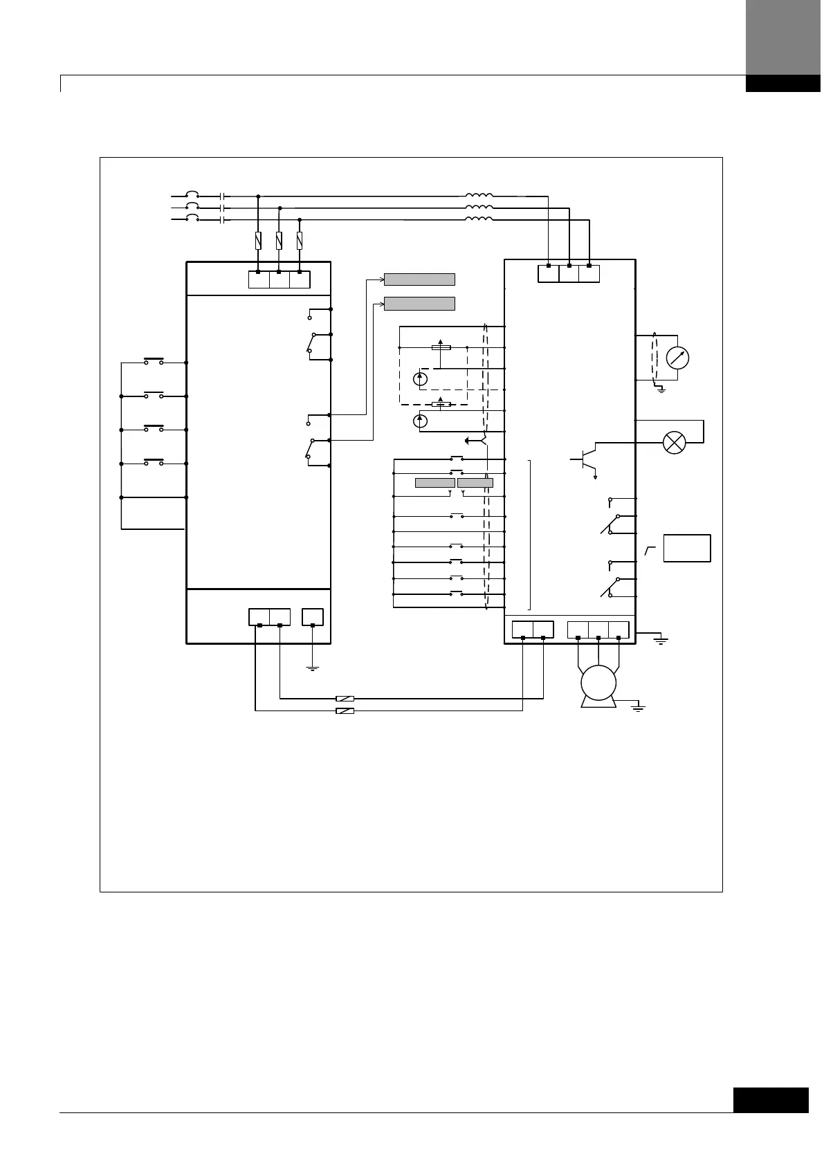
S T
P
R
N
Ground
DI 1:
7
9
10
12
11
DI 3:
DI 4:
DI5:
COM: Common for I/O
DO1.A
Fault_a
AC 1A/250V
DC 1A/30V
DO1.C
DO1.B
21 (B)
23 (COM)
22 (A)
FG
High Speed Fuse
(recommendation)
Run
Enable
External Fault
(A)
Fault Reset
SOHO RCU
*) caution 1 : The cable length between DC Link terminal of inverter and terminal of RCU should be less than 7m. P-N of RCU
and DC Link terminal P(+), N(-) of inverter should correspond.
SOHO VD INVERTER
19
20
IC : 50mA
Ready Relay
24Vout
DC3
21
22
23
DO1.A
DO1.C
DO1.B
Brake Contact
Output
(Open & Close)
AC 1A/250V
DC 1A30V
24
25
26
DO2.A
DO2.C
DO2.B
Fault Contact
Output
AC 1A/250V
DC 1A30V
Forward Run/Stop
Reverse Run/Stop
Enable
External Fault
Fault Reset
Multi-Step Speed Setting 1
Multi-Step Speed Setting 2
Multi-Step Speed Setting 3
7
8
9
10
11
12
13
14
15
16
DI1
DI2
DI3
DI8
DI7
DI6
DI5
DI4
COM
COM
Multi-function
Contact Input
MCMCCB
R
S
T
3-Phase
Power
Supply
380~460V
50/60Hz
Shield
Multi-function
Analog Output
-10 to +10V 2mA
(Output Current)
17
18
0(4)~20mA
lout+
shield
1k ~10kΩ 0.5W
1
2
3
4
5
6
10Vref COM
+10Vref : 10Vdc
Vin1 / lin2+
lin1-
Vin2 / lin2+
lin2-
L2 L3L1
V WU
IM
P N
*) caution 1
*) caution 2
High Speed Fuse
(recommendation)
*) caution 2 : Install Fuse between RCU output terminal (R, S, T) and power supply.
(Refer to chapter 4.5 for wire and fuse specification)
RCU #23
RCU #21
INVERTER #9-1
INVERTER #9-2
#9-1#9-2
*) caution
3
*) caution 3 : When you want to connect inverter with RCU, Connect Healthy (A_contact) signal of RCU with Enable signal of
inverter.
Iout-
16
COM: Common for I/O
Healthy
AC 1A/250V
DC 1A/30V
DO2.C
DO2.B
26 (COM)
25 (A)
DO1.A
DO2.A
24 (B)
*) caution 4
*) caution 4 : You should install a AC input reactor to prevent the regenerated power from flowing to inverter.
ACL
*) caution 5
*) caution 5 : You should link RCU output-side terminals (R, S, T) between main input power and input AC reactor of inverter.
 Loading...