Hitachi America Ltd. RCU SERIES
4.3 Control terminal specific
7
9
10
12
11,16
23
21
22
No Content
RCU operation signal
RCU preparation of operation signal
External fault input signal
RCU fault reset signal
Fault A contact output
Fault B contact output
Terminal
DI. 01
DI. 02
DI. 03
DI. 04
DI. COM
DO1. B
DO1. A
DO1. C
Signal
Contact Input 1
Contact Input 2
Contact Input 3
Contact Input 4
Contact input (common
terminal)
Contact output 1 (b-contact)
Contact output 1 (a-contact)
Contact ouput 1 (common
terminal)
A, B contact common terminal
AC 1A/250V
DC 1A/30V
Contact
Input
Contact
Output
Catalog
26
24
25
Healthy A contact output
Healthy B contact output
DO2. B
DO2. A
DO2. C
Contact output 1 (b-contact)
Contact output 1 (a-contact)
Contact output 1 (common
terminal)
A, B contact common terminal
AC 1A/250V
DC 1A/30V
Contact
Output
Figure 4.2 Control terminal specific
Refer to figure 4.1 for basic connection.
The control cables should be at least 0.5mm
2
shielded cables. The maximum wire size fitting
in the terminals is 2.5mm
2
.
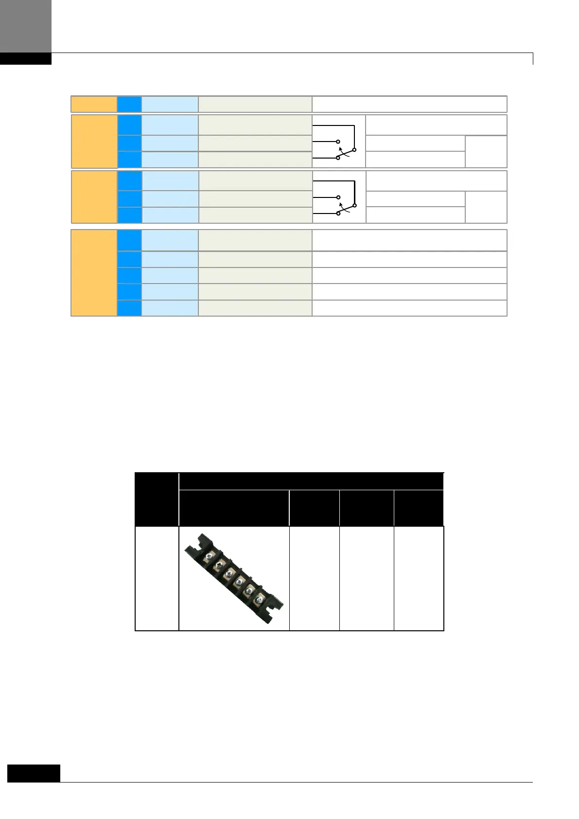
4.4 Terminal block and Screw type (According to Mounting Dimension)
Table 4.1 RCU Terminal Block and Screw type
Call 1(800)985-6929 for Sales
Call 1(800)985-6929 for Sales
 Loading...