Do you have a question about the Hitachi RPI-1.0FSN4E and is the answer not in the manual?
General notes regarding publication reproduction, continuous improvement policy, and responsibility for errors.
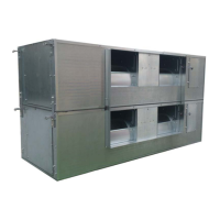
Overview of the product guide, including prior checks and classification of outdoor unit models.
Instruction to check the model name, air conditioning system type, and codes before installation.
Details on classifying outdoor unit models based on type, capacity, refrigerant, and special features.
Information on the power range and combinations of FSXN1E outdoor units.
Information on the power range and combinations of FSXNH outdoor units.
Safety precautions during system design and unit installation to avoid injuries and damage.
Explanation of symbols used to indicate hazardous situations for safety and well-being.
Additional safety information regarding potential dangers and caution points during operation.
Details on high pressure vessel compliance and safety device protection.
Purpose of the manual, emphasizing the need for qualified personnel and safety awareness.
Specifies the designed operating temperature ranges for the heat pump and heat recovery system.
Diagram and list of part names for the RAS-8FSXN1E outdoor unit.
Diagram and list of part names for the RAS-(10/12)FSXN1E outdoor unit.
Diagram and list of part names for the RAS-(14/16)FSXN1E outdoor unit.
Diagram and list of part names for the RAS-(5/6)FSXNH(E) outdoor unit.
Diagram and list of part names for the RAS-(8-12)FSXNH(E) outdoor unit.
Refrigerant cycle diagram and part list for RAS-(8-12)FSXN1E.
Refrigerant cycle diagram and part list for RAS-(14/16)FSXN1E.
Refrigerant cycle diagram and part list for RAS-(5/6)FSXNH(E).
Refrigerant cycle diagram and part list for RAS-(8-12)FSXNH(E).
Guidelines for securely fastening and transporting outdoor units to avoid damage.
Precautions for handling loads with fork-lift trucks to prevent injury and damage.
Instructions for lifting units safely using hoisting slings through base openings.
Specifications for the center of gravity of various outdoor unit models for lifting.
Conditions for outdoor unit placement, considering sunlight, ventilation, noise, and access.
Required installation space around the unit, considering walls and ventilation holes.
Installation guidelines based on surrounding walls in two, three, and four directions.
Specific installation space requirements when walls are present in two directions.
Specific installation space requirements when walls are present in three directions.
Specific installation space requirements when walls are present in four directions.
Considerations for installation dimensions, air flow, and grouping of units.
Guidelines for foundations, anchorage bolts, and securing outdoor units properly.
Requirements for foundations, including height, drainage, and material considerations.
Diagram showing the correct position and securing method for anchorage bolts.
Instructions for selecting appropriate refrigerant pipe sizes based on system type and capacity.
Guidelines for selecting pipe sizes and connection kits for heat pump and heat recovery systems.
Details on copper pipe specifications, sizes, connection methods, and insulation requirements.
General instructions for installing refrigerant pipes, including flared connection mounting and insulation.
Specific pipe connection details for heat pump and heat recovery systems based on model and kit.
Details on pipe connection kits for SET FREE FSXN1E series (2 pipes).
Details on pipe connection kits for SET FREE FSXN1E series (3 pipes).
Precautions for outdoor unit installation, including order of units and pipe installation.
Pipe size specifications for 2-unit combinations of FSXN1E and FSXNH(E) outdoor units.
Pipe size specifications for 4-unit combinations of FSXN1E and FSXNH(E) outdoor units.
Pipe diameter specifications between CH unit and multikit for 3 and 2 pipe systems.
Pipe diameter specifications for 2-pipe systems between multikit and indoor units.
Pipe diameter specifications between multikit and indoor units.
Working conditions and permitted pipe lengths for heat pump systems (2 pipes).
Working conditions and permitted pipe lengths for heat recovery systems (3 pipes).
Procedure for performing an air-tight test on refrigerant piping and stop valves.
Method for calculating additional refrigerant charge based on piping length and indoor unit capacity.
Steps for charging additional refrigerant, including opening stop valves and vacuuming.
System for automatically judging the refrigerant amount and identifying issues.
Step-by-step procedure for checking the refrigerant amount using the automatic system.
Table showing results (sufficient, excessive, insufficient, abnormal) and their remarks.
Safety precautions and concentration limits for refrigerant leaks.
Information on the maximum permitted concentration of HFC gas R410A in air.
Formula and steps to calculate refrigerant concentration in a room.
Guidelines for drainage pipes and condensation management to prevent damage.
Details on condensation drainage systems and the use of optional drainage kits.
General cautions and safety information before starting electrical wiring work.
Verification of electrical components, supply voltage, and wiring connections.
Wiring diagrams for connecting power sources to outdoor and indoor units.
Minimum wire sizes for power source and transmission cables.
Electrical data and recommended wiring/breaker sizes for outdoor units.
Specifications for service voltage, start-up voltage, and voltage imbalance.
Information on maximum allowed system impedance for electromagnetic compatibility.
Harmonics compliance information related to IEC standards.
Instructions for connecting electrical wiring to outdoor units.
Guidelines for connecting power supply, communication cables, and earthing for indoor units.
Location and settings for DSW switches on PCB1 for various functions.
Setting the refrigerant cycle number using DSW1 and RSW1 switches.
Setting the capacity for FSXN1E and FSXNH(E) outdoor units.
Setting the outdoor unit number for combinations, including base units.
Setting the supply voltage for the unit.
Setting communication parameters for H-LINK and H-LINK II systems.
Settings for test run and service operations, including compressor stoppage.
Settings for emergency operation, test run, and service, including refrigerant quantity monitoring.
Setting various functions and external inputs/outputs for the air conditioner.
Details on setting external inputs and outputs, and selecting function numbers.
Procedure to enter the menu mode for setting functions.
Procedure to exit the menu mode and return to normal operation.
Guide to selecting and setting external input/output functions.
Guide to selecting and changing function settings.
Preliminary checks required before performing the test run, including safety and connections.
Procedure for carrying out the test run on indoor units and checking system conformity.
Instructions for using the PC-ART remote controller to perform the test run.
Instructions for using the PC-ARF remote controller to perform the test run.
A checklist for verifying all aspects of the test run operation.
Table listing common alarm codes, categories, content of abnormality, and possible causes.
Details on devices protecting the compressor, including pressure switches and oil heaters.
| Type | Split System |
|---|---|
| Cooling Capacity (kW) | 2.8 |
| Heating Capacity (kW) | 3.2 |
| Refrigerant | R410A |
| Power Supply | 220-240V, 50Hz |