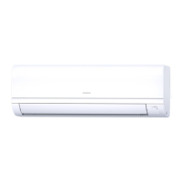
Do you have a question about the Hitachi RPK-3.0FSN3M and is the answer not in the manual?
General notes on publication rights, product changes, and printing errors.
Guide to product identification, model classification, and preliminary checks before installation.
Check model name, system type, codes, and references before installation.
Details on classifying outdoor unit models based on series, capacity, and special types.
Details on power range and combinations of FSXN1E outdoor units based on HP.
Details on power range and combinations of FSXNH outdoor units based on HP.
Important safety information and symbols used in the manual to avoid injury and damage.
Explanation of symbols like DANGER, CAUTION, and NOTE used throughout the manual.
Additional safety precautions regarding electrical hazards, system operation, and component handling.
Information on pressure vessel compliance, safety devices, and warnings related to high pressure switches.
Outlines the manual's purpose and emphasizes the need for qualified personnel and understanding instructions.
Specifies the operating temperature range for cooling, heating, and combined modes for the heat pump/recovery system.
Details the automatic functions of the system, including compressor protection, frost prevention, defrost cycle, and overload prevention.
Identifies and lists the components of the RAS-8FSXN1E outdoor unit with a diagram.
Identifies and lists the components of the RAS-(10/12)FSXN1E outdoor unit with a diagram.
Identifies and lists the components of the RAS-(14/16)FSXN1E outdoor unit with a diagram.
Identifies and lists the components of the RAS-(5/6)FSXNH(E) outdoor unit with a diagram.
Identifies and lists the components of the RAS-(8-12)FSXNH(E) outdoor unit with a diagram.
Illustrates the refrigerant cycle for the RAS-(8-12)FSXN1E model, including component labels and pipe sizes.
Illustrates the refrigerant cycle for the RAS-(14/16)FSXN1E model, including component labels and pipe sizes.
Illustrates the refrigerant cycle for the RAS-(5/6)FSXNH(E) model, including component labels and pipe sizes.
Illustrates the refrigerant cycle for the RAS-(8-12)FSXNH(E) model, including component labels and pipe sizes.
Provides instructions and precautions for safely transporting outdoor units, including fastening and storage.
Details safe handling procedures for units using fork-lift trucks, emphasizing caution and correct insertion points.
Explains the correct method for lifting units using slings, highlighting danger precautions and proper sling placement.
Specifies site conditions, ventilation, access, temperature, noise, and electromagnetic interference considerations for outdoor unit placement.
Details required clearances around the unit for installation and maintenance, considering walls and ventilation.
Provides installation guidelines for units with walls in two, three, and four directions, including spacing requirements.
Discusses space considerations for multiple units, wall proximity, and ventilation to prevent interference.
Covers foundation requirements, anchorage bolt positions, and fastening methods for outdoor units.
Specifies foundation height, drainage, and strength requirements to support unit weight and withstand environmental factors.
Details the location and securing of anchorage bolts for outdoor unit installation, referencing specific models.
Provides guidance on selecting refrigerant pipe sizes based on system type, operating mode, and unit capacity.
Instructions for selecting pipe sizes based on unit connections and cautions against using incorrect sizes.
Details copper pipe specifications, sizes, connection methods, and insulation requirements for refrigeration systems.
Tables detailing pipe connection kits and sizes for various combinations of FSXN1E outdoor units in heat pump and heat recovery systems.
Tables detailing pipe connection kits and sizes for various combinations of FSXNH(E) outdoor units in heat pump and heat recovery systems.
Tables providing pipe sizes for specific 3-unit combinations of FSXN1E and FSXNH(E) outdoor units.
Tables providing pipe sizes for 4-unit combinations of FSXN1E outdoor units.
Tables providing pipe sizes for specific 3-unit combinations of FSXNH(E) outdoor units.
Tables providing pipe sizes for specific 3-unit combinations of FSXNH(E) outdoor units.
Tables providing pipe sizes for specific 3-unit combinations of FSXN1E outdoor units.
Tables providing pipe sizes for specific 3-unit combinations of FSXNH(E) outdoor units.
Details pipe diameters for connections between CH units, multikits, and indoor units for 2 and 3 pipe systems.
Specifies pipe diameters for 2-pipe systems connecting multikits to indoor units.
Details pipe diameters for connections between multikits and indoor units for 2-pipe systems.
Tables showing pipe sizes for base units of FSXN1E and FSXNH(E) for heat pump and heat recovery systems.
Tables detailing pipe sizes for 2-unit combinations of FSXN1E and FSXNH(E) outdoor units.
Tables detailing pipe sizes for 3-unit combinations of FSXN1E and FSXNH(E) outdoor units.
Tables detailing pipe sizes for 4-unit combinations of FSXN1E outdoor units.
Tables detailing pipe sizes for 3-unit combinations of FSXNH(E) outdoor units.
Tables detailing pipe sizes for 3-unit combinations of FSXNH(E) outdoor units.
Tables detailing pipe sizes for 3-unit combinations of FSXN1E and FSXNH(E) outdoor units.
Tables detailing pipe sizes for 3-unit combinations of FSXN1E and FSXNH(E) outdoor units.
Tables detailing pipe sizes for 4-unit combinations of FSXN1E outdoor units.
Tables detailing pipe sizes for 4-unit combinations of FSXN1E outdoor units.
Instructions for operating stop valves, including gas and liquid valves, and tightening torques for flare nuts.
Details stop valve types, tightening torques for connections, and cautions for spindle valve operation.
Illustrates example installation diagrams for 2-pipe and 3-pipe systems with different combinations of units and pipes.
Provides restrictions and guidelines for piping branch connections, including length limits and size adjustments for heat pump and heat recovery systems.
Tables detailing pipe sizes for heat pump systems and heat recovery systems, considering unit combinations and pipe lengths.
Tables detailing pipe sizes for heat pump and heat recovery systems, including unit combinations and pipe lengths.
Details pipe diameters for connections between CH units, multikits, and indoor units for 2 and 3 pipe systems.
Specifies pipe diameters for 2-pipe systems connecting multikits to indoor units.
Details pipe diameters for connections between multikits and indoor units for 2-pipe systems.
Details pipe diameters for connections between CH units, multikits, and indoor units for 2 and 3 pipe systems.
Specifies pipe diameters for 2-pipe systems connecting multikits to indoor units.
Details pipe diameters for connections between multikits and indoor units for 2-pipe systems.
Provides guidelines for piping branch connections, including length limits and size adjustments for heat pump and heat recovery systems.
Details the procedure and precautions for performing an air-tight test on the refrigerant piping system using nitrogen gas.
Instructions for insulating refrigerant pipes and piping covers to prevent damage from weather and animals.
Explains the process of vacuum pumping the refrigerant system, including pressure checks and precautions.
Provides methods for calculating additional refrigerant charge based on piping length, indoor unit capacity, and system configuration.
Table showing maximum additional refrigerant quantities for different HP outdoor units.
Specific calculation method for wall-type units with expansion valve kits, focusing on liquid piping.
Details the procedure for charging additional refrigerant into the system, including stop valve operation and safety precautions.
Diagram illustrating the refrigerant charging process for a heat pump system.
Diagram illustrating the refrigerant charging process for a heat recovery system.
Explains the automatic system for judging refrigerant amount and the procedure for checking results.
Addresses critical gas concentrations and measures to prevent accidental refrigerant gas leakage.
Details safety precautions, maximum permitted concentrations, and calculation methods for refrigerant concentration in rooms.
Outlines room characteristics and ventilation requirements to mitigate risks associated with refrigerant leaks.
Discusses condensation drainage systems, site selection, and the use of optional drainage kits, including safety warnings.
General precautions and safety guidelines related to electrical wiring work, including power disconnection and component protection.
Covers essential checks for electrical components, supply voltage, installation regulations, and proper earthing connections.
Illustrates power source wiring methods for heat pump and heat recovery systems, showing connections to outdoor and indoor units.
Provides tables for minimum wire sizes for power source and transmission cables based on model and power supply.
Details electrical data and recommended wiring, breaker sizes, and switch types for each outdoor unit.
Specifies voltage requirements, start-up voltage, imbalance, and electromagnetic compatibility standards for the units.
Instructions for connecting electrical wiring to the outdoor unit's terminal board and PCB, including screw tightening torques.
Guidelines for connecting power supply and communication cables for indoor units, CH units, and outdoor units.
Connection diagrams for heat recovery systems, showing wiring for indoor units, CH units, and outdoor units.
Explains the location and function of DSW switches on PCB1 for setting refrigerant cycle, unit numbers, and supply voltage.
Details DSW switch settings for refrigerant cycle, capacity, outdoor unit number, supply voltage, communication, and test run configurations.
Guides on setting external inputs/outputs and various operational functions using the remote controller or PCB switches.
Instructions for selecting and setting external input/output functions and operational parameters using push-switches.
Details function settings for items like circulator, night shift, defrost, and compressor frequency control.
Lists essential checks and precautions to be taken before performing the test run, including wiring and refrigerant checks.
Provides the procedure for conducting the test run, including checking stop valves, sequences, and system conformity.
Explains how to use the PC-ART remote controller to perform the test run, including mode selection, fan operation, and alarm handling.
Guides on using the PC-ARF remote controller for test run, including menu display, unit connection checks, and abnormal sound identification.
A checklist for verifying system operation, temperatures, pressures, voltages, and component functions during the test run.
A comprehensive table listing common alarm codes, categories, contents of abnormality, and possible causes for troubleshooting.
Continues the list of common alarm codes, covering outdoor unit abnormalities, inverter faults, fan controller issues, and unit addressing.
Details the devices and combinations that protect the compressor, including pressure switches, oil heaters, and fuse capacities.
General caution regarding refrigerant leaks, smoke, or unusual noises from the unit.
Lists normal operational sounds and minor issues that do not indicate a fault.
Provides basic checks for when the system is not operating, focusing on temperature settings and obstructions.
Offers troubleshooting steps for faulty operation, including airflow obstructions, heat sources, filters, and room conditions.
Instructions on what information to provide to a service supplier if problems persist after basic checks.
| Brand | Hitachi |
|---|---|
| Model | RPK-3.0FSN3M |
| Category | Air Conditioner |
| Language | English |


 Loading...