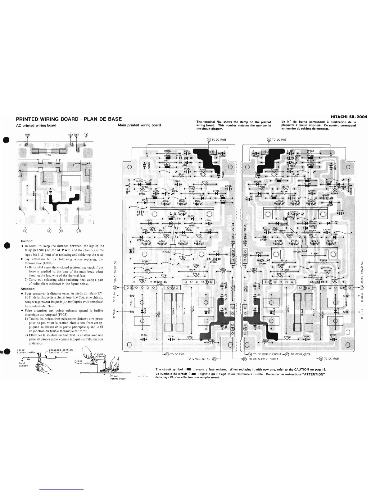
PRINTED WIRING
BOARD·
PLAN
DE
BASE
AC
printed
wiring board
Main
printed
wiring
board
The terminal No. shows
the
stamp
on
the
printed
wiring board. This number matches
the
number in
the
circuit diagram.
HITACHI
51l-2004
Le
N°
de borne correspond a I'indication de
la
plaquette acircuit imprime. Ce numero correspond
au numero du
schema
de
montage.
-t
o
o
--J
~
::0
o
--J
(}l
::0
-i
@ ",1
..
~
;0
If)
o
-i
'll
~
€'I'I.2R
....
~
-i
(j)~'"
r I I .
,;1
i
<D
C721R
~
........
b7~~
.
..
.
Q713R
B~£'
070eR
."
I~c,
."
....
o
.~
Crt3R
~-U
..
R735R 10;'
~.-
~
.;;)
TO
0716R,0717R
Q
00
o
Q.7,IOR
8-¥-E
o
.
--..
.,
R~R
a
-..ho
AE.
R127.
R
-,
,
.'
..
~
,
,..~~
....
Q709R R722R
~~~
, .
R~.
R72,sR '
..
--'
~
87'21R
__
,R719R.
~.
_,
-~
~
...
,.~
, ,
Q708R
R720R.
.E~8~
,,:i
,0702R
•
I~
•
~
TO
DC
SUPPLY
CIRCUIT
TO
DC
SUPPLY
CIRCIT
L7'OIR
~
D103R
.,.,'
.
. R7',3R
,..
~
"
~,
,-
C710R
._,,-
..:
-
R714R,
..
.
--1
...
.
I.··~
C711A
07051',
.R.i.
...
...
,~
........
o'iXl3R
'Q7Q4R
Q7O!)R
o
o
o
""1
o
o
()
:1)
~
6
o
()
;u
.
~
o
-'
0702L
.
~
.
~~e
07'09L
o
0710L
9~E
"
;j
:e
TO
0716L,0717L
R732L
'>
..,
....
o
r
Q7111-
B~E
R722L
----vvv----
R724L
•.
.
~
.~
R721L
~
..,
....
o
N
,..
TO
DC
PWB
C713L
......
VA702L
~
R7iJ'IL
~
~
:s
~.
r
0712L
9~E
RlO6l..
•
C735L.
~~I::..
. ,
RaQ701~
4.
;.:-
~
....
•
E:'~.B
_ R107L
~E:~
~
Q702L
••
o <;705L
~
.......
R7(BL
~
The circuit symbol
(..-
) means a fuse resistor. When replacing it with new
one,
refer
to
the CAUTION
on
page
19.
Le
symbole
de
circuit ( ) signifie qu'il s'agit
d'une
resistance afusible. Consulter
les
instructions
"ATTENTION"
de
la
page
19
pour
effectuer son remplacement.
b
+~i
000
-17-
'R7~L
~
-i
"
r
o
o
~
.~.
ZD705L
Ra
•
",
C~7L
R713l..
,,-
....
'.
...
...
~
R739L R717L
C7I<11-
:S~~~
.-t
4>
. ,
__
.....
, '
C710L
07061- 'R714L
0705L'"
1!
R748L
.....
B~E
~.
..
.•
• 0703L
R711L.
..
~.~
..
_.
0710L 07051-
0704L
07'OpL
R712L.
• .1 •
B~E
B~E
B~E
•.
- •
~LQ]
.
..
[QJ
.-J'"
VA70IL
C712L .
0:
'~.
'~'::
'''~L.
•
0.'
.
20702L
..
C720L
.
...
.
~
.......
Z0704L
R740L .
~
~'h
R72.6L
~L
•
..
R735..1-
• .
.---=----w;,...
r
'.
D71~I-~LE
!;j
1 I
r
~
R'725L
•
\HI,
•
~~
R720L
~B~E
i
""'"
,070BL
I
;><
i
o
--J
(}l
r
-t
o
o
--J
E
r
C7
1
91-
- +
..,...
-i
::,
..
I
@I
r
®
-i
"
r~(])
CD
I I
---1.1-
I
Plier
P
inoes
radio
6)
(8)
(9
I
~
Caution:
• In
order
to
keep the distance between the legs
of
the
relay
(RY901)
on the
AC
PW.B.
and
the
chassis, cut the
legs a bit
(1.5
mm) after replacing and soldering
the
relay.
• Pay
attention
to the following when replacing the
thermal fuse
(F903).
I)
Be
careful since the enclosed section may crack if the
force
is
applied
to
the base
of
the main body when
bending the lead wire
of
the thermal fuse.
2) Carry out soldering while radiating
heat
using a pair
of
radio pliers as shown
in
the figure below.
Attention:
•
Pour
conserver la distance entre les pieds du relais (RY
901),
de
la
plaquette acircuit imprime C.A.
et
Ie
chassis,
couper
legerement les
pieds(l,smm)apres
avoir remplace
les soudures de relais.
• Faire
attention
aux points suivants
quand
Ie
fusible
thermique
est
remplace
(F903).
1)
Toutes
les precautions necessaires doivent etre prises
pour
ne pas briser la section close
si
une force est ap-
pliquee
au
chassis de la partie principale quand
Ie
fi1
de
jonction
du fusible thermique
est
tordu.
2)
Effectuer
la soudure en
emettant
la chaleur avec une
paire de pinces
rarlio comme indique sur l'illustration
ci-dessous.
.'
I>
Plier
Enclosed
section
Pinces
radio~
~Section
close
IA
~
e
-
e
 Loading...