EasyManua.ls Logo

Hitachi SR-2004 Service Manual

Hitachi SR-2004
38 pages
Go to English
To Next Page IconTo Next Page
Page #1 background imageLoading...
Page #1 background image
.,
SERVICE
MANUAL
English
Franc;ais
No. 128
SPECIFICATIONS
FM
SECTION
85 dB
45 dB
I dB
60 dB
50dB(I
kHz)
70
dB
70
dB
28
dBf(14pV)
300
ohms
balanced, 75 ohms unbalanced
Frequency range
Usable sensitivity
50 dB Quieting sensitivity
Signal-to-noise
ratio
(at 6S dBf)
Harmonic
distortion
(at
6S dBf)
NARROW 100
Hz
I kHz
6
kHz
WIDE
100
Hz
I kHz
6 kHz
Frequency response
Image response
ratio
Spurious response
ratio
IF response
ratio
Alternate channel selectivity
NARROW
WIDE
Capture ratio
AM
suppression
Stereo
separation
Sub
carrier suppression
SeA
rejection
Muting threshold
Antenna
input
88
- 108 MHz
Mono: 8.7
dBf
(1.5pV)
Mono: 12.5 dBf (2.3pV)
Mono:
75
dB
Mono: 0.15%
Mono: 0.1%
Mono: 0.25%
Mono: 0.15%
Mono: 0.07%
Mono: 0.2%
30
Hz-IS
kHz
C~:~
aG)
115
dB
120
dB
I]
5
dB
Stereo: 24
dBf
(8.9pV)
Inside the parenthesis
IHF
'58
Stereo: 36
dBf
(34.5pV)
Stereo:
70dB
Stereo:
0.25%
Stereo: 0.2%
Stereo: 0.3%
Stereo:
0.25%
Stereo: 0.1%
Stereo: 0.3%
-.
STEREO
RECEIVER
November 1977
Question and Answer IconNeed help?

Do you have a question about the Hitachi SR-2004 and is the answer not in the manual?

Hitachi SR-2004 Specifications

General IconGeneral
BrandHitachi
ModelSR-2004
CategoryStereo Receiver
LanguageEnglish

Summary

Specifications

FM Section

Technical specifications for the FM receiver section.

AM Section

Technical specifications for the AM receiver section.

Audio Section

Technical specifications for the audio output and input.

Description of the New Circuit

SAW Filter

Details the SAW and ceramic filters used for IF band selection.

Dynaharmony (Class G Amplifier) Output Circuit

Explains the Class G amplifier design for improved efficiency.

Current Mirror Circuit

Describes the current mirror circuit for push-pull output stage.

Constant Current Circuit

Explains the circuit stabilizing amplifier bias.

Idle Current Compensation Circuit Against Power Supply Voltage Fluctuations

Details circuit for stabilizing idle current against voltage changes.

Protection Circuits

Overview of various protection circuits implemented in the unit.

Muting Circuit

Explains the circuit that delays speaker connection to prevent clicks.

ASO (Area of Safety Operation) Detection Circuit

Describes the circuit protecting output transistors from damage.

DC Voltage Detection Circuit (Speaker Protection)

Explains the circuit protecting speakers from DC voltage faults.

Disassembly and Replacement

Removing the Upper Cover, Front Panel & Bottom Plate

Steps to remove the main external chassis components.

Removing the Meters

Instructions for removing the front panel meters.

Removing the Printed Wiring Boards and Output Transistors

Steps to remove internal circuit boards and output transistors.

Circuit Diagrams and Layouts

Printed Wiring Board Layouts

Diagrams showing the layout of various printed wiring boards.

Tuner Circuit Diagram

Detailed circuit diagram of the tuner section.

IF P.W.B. Circuit Diagram

Circuit diagram for the IF printed wiring board.

DC P.W.B. Circuit Diagram

Circuit diagram for the DC power supply printed wiring board.

Main P.W.B. Circuit Diagrams

Circuit diagrams for the left and right main printed wiring boards.

Alignment Procedures

FM Tuner Alignment

Step-by-step alignment procedures for the FM tuner.

AM Tuner Alignment

Step-by-step alignment procedures for the AM tuner.

IF Discriminator and AM IF Alignments

Alignment steps for FM IF discriminator and AM IF.

Audio Circuit Alignment

Idle Current Adjusting Points

Points for adjusting idle current in the audio circuit.

Test Conditions

Test conditions for audio circuit alignment.

Meter Adjustment

Meter Sensitivity Adjustment

Procedure for adjusting the meter sensitivity.

Replacement Parts List

Capacitors

List of capacitors used in the device, categorized by PWB.

Resistors

List of resistors used in the device, categorized by PWB.

Transistors and Diodes

List of transistors, diodes, and thyristors used in the device.

Variable Resistors

List of variable resistors used in the device.

Coils & Transformers

List of coils and transformers used in the device.

Front and Rear Panel Layout

Front Panel Controls and Indicators

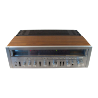
Identifies front panel knobs, switches, indicators, and jacks.

Rear Panel Terminals and Connections

Identifies rear panel terminals, sockets, and antenna connections.

Related product manuals