~
HITACHI
SR-2004
CAUTION
1.
Since simple adjustment
of
MF201 components has been performed before shipment, IF adjustment
is
not required.
When
replacing the MF201, however,
use
an
MF201 with the same color marking
as
that
of
the MF203.
2.
As
the result
of
the adjustment step 6, the best point
of
adjustment from step 5 will
be
shifted a bit. Repeat the adjust-
ment
of
step 5 and 6 until the deterioration becomes minimum and the pointer
of
tuning meter
is
in its center.
3. After setting IF
BAND SELECTOR sw. to
WIDE
and making the signal
of
L ch and Pilot, adjust R322
so
that the out-
put
wave
form
of
R ch becomes min.
Set IF
BAND SELECTOR
sw.
to NARROW and making the signal
of
L ch and Pilot, adjust R323
so
that the
output
wave
form
of
R ch becomes min. Optimize R322 and R323
so
that the leak level
of
the L ch signal
is
equal to that
of
the R ch signal.
ATTENTION
1.
Etant qu'un reglage simplifie des composants de MF201 a ete fait avant l'envoi de l'appareil, un reglage
de
IF n'est pas
indispensable. Cependant, quand MF201 doit
etre remplace, utiliser un MF201 comportant la
me
me
couleur que celle
de
MF203.
2.
A la suite du reglage decrite en 6,
is
meilleur reglage decrit en 5 sera legerement decaIe. Renouveler les reglages 5 et 6
jusqu'a
ce
que les deteriorations soient minimum
et
que l'aiguille
de
l'indicateur d'accord soit en position centrale.
3.
Apres avoir
regIe
Ie
selecteur
de
bande
IF
sur la position "WIDE"
et
avoir regle
Ie
signal du canal gauche
Let
Ie
signal
pilote, ajuster R322 pour que la forme d'onde
de
sortie du canal droit R soit minimale.
Regler
Ie
selecteur
de
bande IF sur la position "NARROW" et regler
Ie
signal
du
canal gauche
Let
Ie
signal pilote puis
ajuster R323 pour la forme d'onde
de
sortie du canal droit R soit minimale. Rendre R322 et R323 optimum pour que
Ie
niveau
de
crete du signal
de
canal gauche L soit egal a celui du canal droit R.
AM
TUNER
ALIGNMENT·
REGLAGE
DE
TUNER
AM
e
Condition
Function
AM
Modulation
400
Hz
30'X
Connection
Setting
Adjust
for
Connexion
Montage
Reglage
pour
Sequence
Input
Output
Tuning
Signal
Adjust
Entree
Sortie
Indicateur
d'
accord
Reglage
Indication
@
@
8
0
0
8
;/)
8 0
IF
Amp.
out
lK
TP
6 IN
lli
x
1
Amplificateur
~T
•
.
~
455kHz
MF251
de
frequence
~lu
intermediaire
Termi.l
V. C. )
CAUTION
(1)
Ferrite
REC
out
or
SP
out
600kHz
600kHz
T252
2
Covering
Antenna
j
Guipage
eom
1400kHz
1400kHz
TC7
Vmax
$
I
Ferrite
600kHz
600kHz
Antenna
CAUTION
(2)
3
Tracking
T252
Alignement
J
1400kHz
TCG
1400kHz
TC8
-
CAUTION
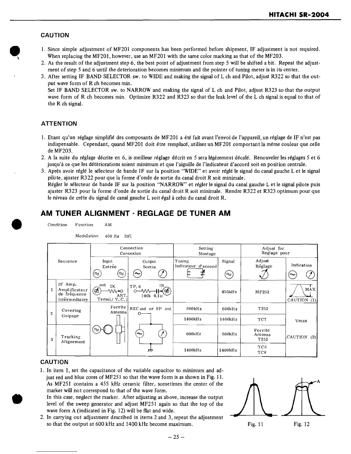
I.
In item
I,
set the capacitance
of
the variable capacitor to minimum and
ad-
just red and blue cores
of
MF251
so
that the wave form
is
as
shown
in
Fig.
II.
As
MF251 contains a 455 kHz ceramic filter, sometimes the center
of
the
marker
will
not
correspond to that
of
the
wave
form.
In this case, neglect the marker. After adjusting
as
above, increase the output
level
of
the sweep generator and adjust MF251 again
so
that the top
of
the
wave
form A (indicated in Fig. 12) will be flat and wide.
2.
In carrying
out
adjustment described in items 2 and 3, repeat the adjustment
so
that the
output
at 600 kHz and 1400 kHz become maximum.
-25
-
Fig.
II
Fig. 12
 Loading...