Do you have a question about the Hitachi VK-S454 and is the answer not in the manual?
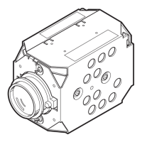
Technical specifications of the camera, including signal, scanning, sensor, and resolution.
Step-by-step instructions for disassembling the camera unit and its components.
Lists essential test equipment, jigs, and charts required for performing circuit adjustments.
Guide on how to start and operate the SMAP software for camera adjustments.
Covers data initialization, electronic volume, auto iris, white balance, and chroma gain adjustments.
Details autofocus adjustments (tracking, noise level, zoom trace) and spot noise correction.
Steps for performing the IR control adjustment for proper infrared functionality.
Lists common error messages for circuits/functions, with countermeasures and troubleshooting steps.
Visual representation of mechanical components and their assembly order with part references.
Catalog of mechanical components, including part numbers and descriptions for replacement.
Comprehensive list of electrical components, specifying part numbers and values.
Diagram illustrating the internal wiring and signal flow between camera modules.
Displays typical signal waveforms at various test points for diagnostic analysis.
Detailed layout of the PC circuit board, showing component placement and routing.
Layout diagrams for SP and CSR circuit boards, showing component positioning and trace paths.
Functional block diagram of the camera system, showing major modules and data flow.
Table detailing the function of each pin on the digital microprocessor unit.
| Operating Temperature | -10°C to +50°C |
|---|---|
| Operating Humidity | 20% to 80% (non-condensing) |
| S/N Ratio | More than 50 dB |
| Day/Night | Yes |
| Wide Dynamic Range | Yes |
| Video Compression | H.264, MJPEG |
| Frame Rate | 30 fps |
| Network Interface | 10/100Base-TX |
| Protocols | HTTP, FTP, SMTP, DNS, DDNS, NTP, RTP |
| Power Supply | DC 12V |