SPC (Supplementary Power Connection) System
Telemetry System
Hitec’s exclusive optional receiver power system allows you to directly power the receiver from the main
motor
power battery of an electric powered aircraft. Up to 35 Volts can be fed directly into the receiver to power
JUST THE RECEIVER FUNCTION. It will not power the servos. Almost all servos will burn-up if more than 6 Volts
are used over a short period of time.
The Hitec Spectra 2.4 Module and Optima Series receivers feature full telemetry capabilities (except Optima 6)
and include a Low Receiver Battery Warning as a basic function.
I. Basic Function: Low Onboard Battery Warning - for All Optima Receivers
When Optima series receiver powered up, it will automatically detect the battery voltage level and
recognizes between 4 cell or 5 cell NiMH and NiCd batteries. (4 cell < 5.8V < 5 cell)
In case of 2cell LiPo battery is being used you can customize the battery warning level by using HPP-22 PC
program.
- When battery level is safe (4 cell > 4.5V, 5 cell > 5.6V): no changes for LED lights.
- When battery level is low (4 cell < 4.5V, 5 cell < 5.6V): Blue LED glows constantly and the red LED will
blink fast. You will hear three-continuous beeping alarm from the module as a low receiver battery warning.
Upon hearing the alarm, we advise you to land at once.
II. Optional Functions:
GPS, FUEL, TEMP, O-RPM, M-RPM, VOLT, Amp Sensors - Applicable for Optima 7 & 9 Only
- There are more devices available in the future. Check the Hitec website at www.hitecrcd.com for more
up-to-dated information.
SERVOSERVO
SERVOSERVO
SERVO SERVO
Power Battery
Motor
BEC
ESC
BAT/CH7
CH6
DATA
SPC
LED
LINK
LED
LINK
CH1
CH2
CH3
CH4
CH5
OPTIMA
OPTIMA 7
2.4GHz 7 Channel Aircraft Receiver
2.4GHz 7 Channel Aircraft Receiver
2.4GHz 7 Channel Aircraft Receiver
AFHSS
2.4GHz
Telemetric
ADAPTIVE
FREQUENCY HOPPING
SPREAD SPECTRUM
SPC Connection Diagram
- Low Battery Warning function is only for your references the actual battery level could be
dierent. Especially Battery Memory Eects, also known as Lazy Battery Eect or Battery
Memory, could aect Low Battery Warning function to be worked properly.
- When 2.4GHz system and HV servos are used together, we strongly recommend using large
capacity battery pack with fully charged condition, and constantly monitor the battery status.
Warning
- Some Hitec servos are rated to be used at 7.4Volts. You will still need to supply power for your
servos with a four or ve cell NiMH receiver battery or 2 cell Li-Po and regulator set-up.
- The SPC system was partially created to be integrated into future Hitec telemetry system devices.
Check the Hitec web site for more information on the availability of telemetry systems in the future.
Note
- If FAIL-SAFE is deactivated, the FAIL-SAFE position settings are also deleted!
- The FAIL-SAFE settings should be checked every time before you run the engine/motor.
Note
FAIL-SAFE and Hold Mode Setup
If you use the FAIL-SAFE function, and set it up properly, should the receiver signal somehow be interrupted or
interference were to occur, the servos will move to your pre-set FAIL-SAFE point you previously stored in the
receiver during the FAIL-SAFE set-up.
If FAIL-SAFE has not been activated, the signal is switched o after the HOLD period of 1 sec. This means that
the servos become “soft” and remain in their last commanded position under no load (this may equate to
full-throttle!), until a valid signal is picked up again.
In the interests of safety, we recommend that FAIL-SAFE should always be activated, and the FAIL-SAFE settings
should be selected so as to bring the model to a non-critical situation. (e.g. motor idle / electric motor OFF,
control surfaces neutral, airbrakes extended, aero-tow release open, etc.)
Testing the FAIL-SAFE Setting
a. Move the sticks to positions other than the FAIL-SAFE settings, and then switch o the transmitter.
The servos should now move to the FAIL-SAFE positions previously stored, after the I sec HOLD period
How to turn FAIL-SAFE O and reactivate the Hold Mode
a. Switch on the transmitter, then the receiver. Wait for the system to boot and you have control over the model.
b. Press and hold the receiver function button for 6 seconds and release it. After 2 seconds the red and
blue LEDs will blink rapidly.
c. Immediately press the button once.
d. FAIL-SAFE Mode is now deactivated and HOLD mode is activated.
e. Turn the transmitter o, then the receiver o.
f. Turn the system back on to use it.
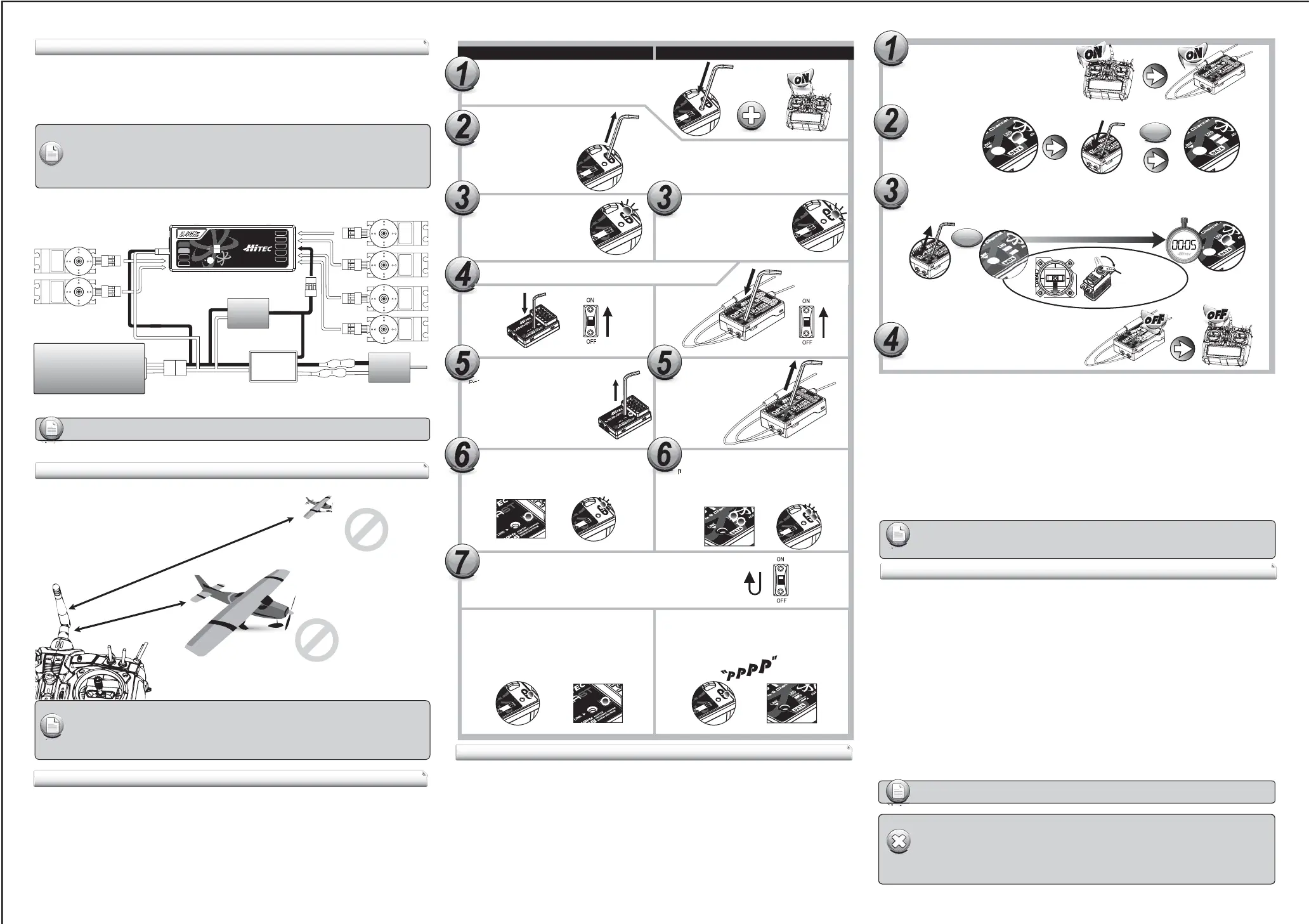
Fail-Safe position
Switch on both.
Wait for the system to boot and control over
the model.
Press and hold the button on the receiver until LED turns o
(approx. 6 second)
Release the button. After 2 seconds both red and blue LEDs blink alternately.
the receiver will count 5 seconds during that time move all the transmitter
sticks and other controls to the desired FAIL-SAFE positions
(e.g. motor idle, control surfaces neutral), and hold until blink stops.
When Blink stops the system will temporary
remember the FAIL-SAFE position, turn o
the system to save and exit.
www.hitecrcd.com
Link (ID-Setting)
Too Close: Less than 50Cm(18in)
Too Far: More than 5M(15ft)
- Link must be done within 15ft(5m). of the transmitter and receiver.
- Transmitter and receiver need to be at least 18in(50cm). from each other to link properly.
Note
Press and hold the link button on Receiver and turn on the power.
Press and hold the button on the module,
and turn on the transmitter.
Both RED, BLUE LEDs will blink rapidly
to nd the transmitter signal.
Release the link button when
RED LED on receiver glows steady.
When the link is completed, BLUE LED on the
module will blink while BLUE LED on the receiver
glows steady.
Release the link button.
Check if BLUE LED is blinking.
If RED LED is blinking, press
the link button for 2 sec., so
that LED changes to the BLUE.
Release the link button.
When the link is completed, BLUE LED on the
module will blink while RED LED on the module
glows steady.
2.4GHz 6 Channel
Aircraft Receiver
2.4GHz 6 Channel
Aircraft Receiver
Channel
eceiver
Check if RED LED is blinking.
If BLUE LED is blinking,
press the link button for 2 sec.,
so that LED changes to the RED.
Non-telemetry RXs (MINIMA & MICRO Series) Telemetry RXs (OPTIMA Series)
Link (ID-Setup or Bind)
Your Hitec AFHSS system uses a communication protocol that links and binds the Hitec 2.4GHz receiver to
your transmitter. Once the receiver and module are “bound”, no other transmitter can interfere with your
receiver during its operation. In the case of multiple model memory transmitters, you can bind as many Hitec
2.4GHz receivers to your transmitter, one per model memory as necessary.
Each module and receiver set is paired at the factory for your convenience.
Use one of the following binding methods to bind additional Hitec 2.4GHz receivers to your transmitter.
For receiver, both BLUE & RED LEDs will glow steady.
Note
- The SPC function is applicable for OPTIMA series receivers only.
Note
- The telemetry function is applicable for OPTIMA series receiver only
2Sec.
6Sec.
When they are turned on again, RED LED on the
module(or radio) and BLUE LED on the receiver
will glow steady.
When they are turned on again, you can hear
continuous beep sound. Both RED LEDs on the
module and receiver will glow steady
in normal status.
Channel
eceiver
To save the setting, please reboot both transmitter and receiver.
 Loading...