11
DEFROST (Heat pump systems)
At low outdoor temperature during heating cycle and
depending on air humidity, frost will appear on the
outdoor coil. It is necessary to remove the ice for proper
continuation of the heating cycle. This is done auto-
matically with a device, operating in function of time
and temperature of the surface of the heat exchanger,
producing defrost by hot gas injection.
During this cycle, the auxiliary electrical heating coil
(option) is connected to compensate for heating. For
units with two compressors, the automatic defrost is
independent for each refrigeration circuit.
FANS
When static pressure and air flow requirements differ
from nominal ratings, centrifugal fan speed can be
adjusted to obtain specific air flow and static pressure.
Consult fan curves shown in the technical manual.
For proper and reliable operation of the system, air
flow should within ± 10% of the nominal air flow indi-
cated on the fan curves.
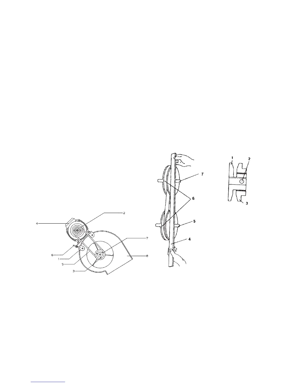
To change fan speed:
1- Slide the motor along it's track to remove the trans-
mission belt.
2- Loose the motor pulley set screws 2 and rotate pul-
ley flanges as necessary.
3- Tighten set screws 2.
4- Replace transmission belt(s) in the pulley channel.
5- If needed, tighten the belt(s) using tension screw
nut and washer 6. Refer to Fig. 4.
1- Motor support 5- Transmission belt
2- Motor pulley 6- Tensor screw
3- Set screw 7- Fan pulley
4- Motor 8- Fan scroll
Fig. 4 - Fan speed adjustment
1- Fixed flange
2- Set screw
3- Movable flange
4- Ruler straight edge must be par-
allel with the belt.
5 + 7- Motor and fan shafts has to
be parallel
6- Pulleys
In order to align motor and fan pulleys:
1- Loose fan pulley set screw, slide it along the pulley
shaft and align with the motor pulley using a ruler to
check that is in parallel position to transmission belt
(see Fig. 5).
2- Tighten fan pulley screws.
Fig. 5 - To align motor and fan pulleys.