8
SPLIT SYSTEMS VERSION
REFRIGERANT LINES
CONNECTIONS AND
REFRIGERANT CHARGE
Units are shipped from the factory with nitrogen
charge and soldered piping connections. Piping con-
nections should be made by qualified installer.
IMPORTANT
To connect outdoor with indoor unit always use
degreased and deoxidized copper refrigerant grade
tubes.
When making refrigerant pipes connections it is nec-
essary to respect the following:
- Avoid small radius curves.
- Take away the nitrogen holding charge from the
refrigerant circuit.
- Select the diameter of the copper tubing taking in
consideration the distance between the indoor and
outdoor units and the unit type.
- For soldering, use silver alloy rod and be sure that
it is done in a nitrogen atmosphere.
- Insulate the refrigerant lines to avoid damage and
oxydation.
- Pull a vacuum in the refrigerant circuit till obtain-
ing a pressure of 0.7 mm water gauge (6.9 Pa) and
maintain it for at least 2 hours.
- Charge the refrigerant circuit with the necessary
amount of refrigerant. Refrigerant charge indicated
in the technical manual is sufficient for the outdoor
and indoor units, you have to add the refrigerant quan-
tity needed for the piping, using table 1 in accordance
with the piping length and diameter.
- Check for refrigerant leaks.
ATTENTION
For correct unit performance and longevity never un-
der or overcharge refrigerant.
IMPORTANT
- Never use a compressor as a vacuum pump.
- Liquid refrigerant must never be introduced into the
suction line.
REFRIGERANT LINES SELECTION
When designing refrigerant lines you have to consider
different piping arrangements:
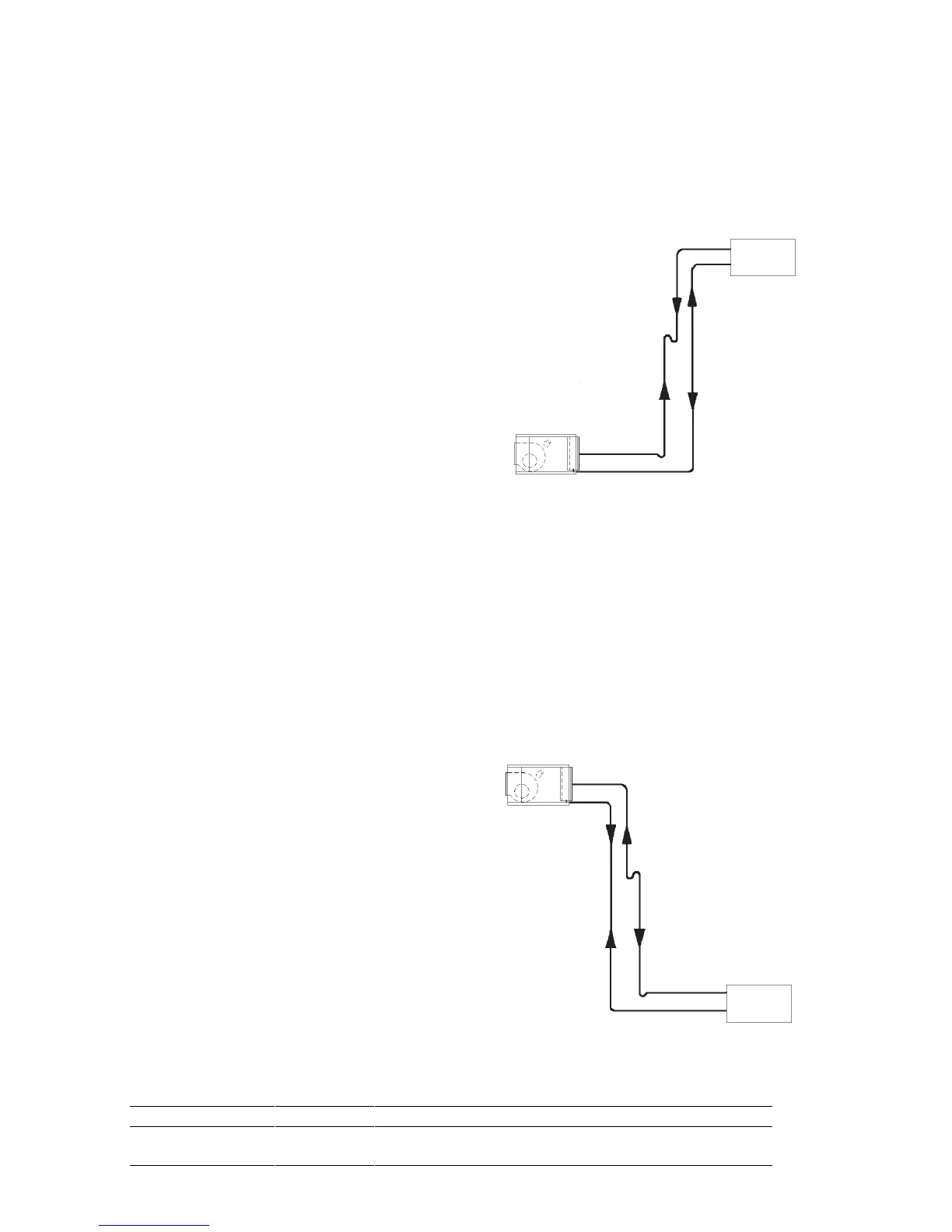
LAYOUT ACCORDING TO FIGURE 2
Suction / discharge line - Vertical run
- A trap at the base of the vertical pipe run and in-
termediate traps every 8 meters.
- Suction line, vertical run: gas velocity should be
more than 6 m/s.
LAYOUT ACCORDING TO FIGURE 3
Indoor
unit
Outdoor
unit
Heat pump Heat pump (discharge line)
Liquid line Gas line
Cooling Cooling (suction line)
Fig. 3 - Outdoor unit is below the indoor unit.
Heat pump Heat pump
(discharge line)
Gas line Liquid line
Cooling Cooling
(suction line)
Fig. 2 - Outdoor unit is installed above the indoor unit.
Outdoor
unit
Indoor
unit
Table 1:ADDITIONAL REFRIGERANT CHARGE (g/m)
Diameter 1/4" 5/16" 3/8" 1/2" 5/8" 3/4" 7/8" 1-1/8" 1-3/8" 1-5/8"
Liquid line 15 25 40 75 120 180 250 420 645 965
Suction line - - 6 14 23 34 47 81 123 185