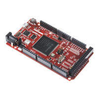
The ShieldBuddy TC275 is a development platform designed by Hitex (U.K.) Limited, based on the Arduino Due (SAM3X) form factor, but featuring an Infineon Aurix TC275 32-bit triple-core microcontroller. This manual, version 2.4, released in May 2015, provides comprehensive information for users, including basic setup, programming, and hardware details.
Function Description
The core function of the ShieldBuddy TC275 is to provide a powerful development environment for applications requiring a 32-bit triple-core microcontroller, leveraging the familiar Arduino IDE and its extensions. Unlike typical Arduinos with a single processor, the ShieldBuddy TC275 offers three independent cores (Core 0, Core 1, and Core 2) for multicore programming. Core 0 runs the standard setup() and loop() functions, while Core 1 and Core 2 execute setup1()/loop1() and setup2()/loop2() respectively. This allows for simultaneous execution of three applications.
The TC275 processor architecture includes a GTM (General Purpose Timer Module) for advanced timer and PWM functions, multiple serial ports (ASCLIN), CAN interfaces, I2C, SPI, and ADC/DAC peripherals. The development platform supports a range of DSP-like functions through the Infineon "TriLib" library, which consists of highly optimized assembler-coded routines callable from C and C++ programs.
A key feature is the Ethernet BootLoader/In Application Ethernet Flash Programmer, which enables programming the TC275 PFLASH via an Ethernet shield using TFTP. This provides an alternative to USB programming, although it's noted that the bootloader is not 100% robust and interruptions can lead to an incomplete or damaged application.
Important Technical Specifications
- Microcontroller: Infineon Aurix TC275 32-bit triple-core.
- Core Speed: Cores 1 and 2 are approximately 20% faster than Core 0 due to an extra pipeline stage.
- Memory Map: Single memory space (0x00000000 – 0xFFFFFFFF) accessible by all three cores, including FLASH and RAM areas.
- Serial Ports: 4 potential hardware serial ports, including SerialASC (default for Arduino IDE Serial Monitor), Serial1 (RX1/TX1 on J403 pins 17/16), Serial0 (RX0/TX0 on J403 pins 15/14), and Serial (RX/TX on J402 pins D0/D1).
- ADC Read Resolution: Default 10-bit, configurable to 8-bit or 12-bit. Fast ADC conversions can achieve up to 600ksamples/sec.
- PWM: Supports custom PWM frequencies and fast updates of
analogOut() functions. The GTM TIM modules provide 9 general-purpose timers for periodic interrupts, with periods ranging from 1us to 170 seconds.
- DAC: Two 14-bit DAC pins (DAC0 and DAC1) for analog output.
- CAN: Three independent CAN channels (CAN0, CAN1, CAN3) with support for 11-bit and 29-bit IDs.
- I2C/Wire: Default I2C peripheral on pins 20 (SDA) and 21 (SCL), with alternative pins on 6 (SDA) and 7 (SCL), and SDA1/SCL1. Supports master mode only. Default baudrate is 100kbit/s, configurable up to 400kbit/s. Software-driven I2C is also available for additional channels.
- SPI: Three independent SPI channels: Default SPI (on P201.1, P201.4, P201.3 with P10 as CS), SPI Channel 1 (on p12, p11, p13 with P10 as CS), and a bit-bashed SPI Channel 2 (on p50, p51, p52 with P53 or P10 as CS) running at about 3mbit/s.
- EEPROM: Supports EEPROM functions for non-volatile data storage.
- Power: Can be powered from USB or 6V to 9V via the jack socket. A switch (S501) selects the power source. The VIN pin provides 9-12V input with a maximum continuous current of 1.5A.
- Safety Version (CIC61508): Programmed with VANIA3.2 firmware release.
Usage Features
- Arduino IDE Integration: The ShieldBuddy TC275 is designed to be used with an extended Arduino IDE, allowing developers familiar with Arduino to easily transition to multicore programming.
- Multicore Programming: Provides
setup1()/loop1() and setup2()/loop2() functions for programming Core 1 and Core 2, enabling parallel execution of tasks. Global variables can be used for inter-core communication and synchronization.
- Interrupts: Supports triggering interrupts in other cores, facilitating coordination and communication between cores. General-purpose timer interrupts are also available for periodic function calls.
- Memory Management: Macros are provided to easily place variables into specific SRAM areas (CPU1, CPU2, LMU RAMs) for performance optimization, especially for the faster Core 1 and Core 2.
- Fast I/O:
digitalRead() and digitalWrite() functions are optimized for faster execution.
- Analog Functions:
analogWrite() and analogOut() functions are available, with support for custom PWM frequencies.
- PWM Measurement: Functions to measure PWM period, duration, duty ratio, and frequency.
- DSP Library: Access to Infineon's "TriLib" library for optimized DSP-like functions.
- Ethernet Programming: TFTP-based bootloader for programming via Ethernet, allowing for remote updates.
- Debugging: Supports debugging programs using the Eclipse IDE with the PLS UDE Debug Perspective, requiring specific configuration based on the TC275 step (CA or DC).
Maintenance Features
- Firmware Updates: The Ethernet bootloader allows for in-application flash programming, although caution is advised due to potential for incomplete updates.
- Restoring Erased FLASH: A procedure involving jumper JP201 is provided to temporarily enable the debug interface, allowing reprogramming of the PFLASH if it becomes completely erased or bootmode headers are damaged.
- Board Test: A basic board test procedure is outlined to verify CPU functionality, involving programming a specific hex file and using a terminal program to check output and LED behavior.
- Documentation and Support: The user manual provides detailed instructions and examples. An online forum (ShieldBuddy.boards.net) is available for community support.
- Feedback Mechanism: Users are encouraged to provide feedback on the document to help improve its quality.
The ShieldBuddy TC275 aims to bridge the gap between the simplicity of Arduino development and the power of Infineon's Aurix multicore microcontrollers, offering a robust platform for advanced embedded applications.