APL-2 Series Limit Switch Box
Installation Operation & Maintenance Manual
Doc No. : HUMG-APL2-16 Rev0 Page 8 / 10 Valve Automation Leader HKC
8 Maintenance
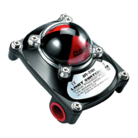
HKC APL 2..N Series limit switch box is designed to provide accurate and reliable valve position signaling and
indicating of most valves or actuators manufactured
Caution :
Shut off incoming power or air supply on the valve actuator before maintenance limit switch box.
Be sure that the area is clean before disassemble and maintenance limit switch box. Clean all parts and
housing before re-assemble.
Refers to the part list when ordering replacement or spare parts.
Maintenance, under normal conditions at six month intervals or 100,000 cycle operation. But when conditions
are more severe, more frequent inspections may be required.
Ø Ensure valve actuator alignment
Ø Ensure wiring is insulated, connected and terminated properly
Ø Ensure all screws are present and tight
Ø Ensure conduit connections are installed properly and are dry
Ø Check internal devices for condensation
Ø Check enclosure O rings seals and verify that the O ring is not pinched between housing
Ø Visually inspect during open/close cycle
Ø Inspect identification labels for ware and replace if necessary
Warning :
Treat cover with care. Gap surface must not be damaged or dirtied in any way
9 Inspection
Ø Check the item and quantity of products with packing list or related documents.
Ø Check the limit switch box o-ring. Where a damage on it. It caused the corrosion of internal parts.
Ø Check the adjustment of cams. Cams shall be released when those have been used for a long period of
operating. If do so, they don’t work correctly with switches.
10 Storage
The products must be stored in a clean, cool and dry area. The unit shall be stored with the cover installed and
the cable entry openings sealed. Storage must be off the floor, covered with a sealed dust protector.
11 Trouble Shooting
The following instructions are offered for the most common difficulties encounter during installation and start-
up.
Signal fails to main control room.
Ø Check the wiring of limit switch box in accordance with wiring diagram.
Ø Check where the cams or switches are damaged or broken.
Ø Check the main signal wire from the terminal strip.
Ø Re-set the limit switch box
12 Tools
Ø 1 Set Metric Allen key (Hex Wrench)
Ø 1 Set Screw drivers
Ø 1 Set Metric spanner
Ø 1 Wire Stripper long nose
Ø 1 Needle nose pliers
Ø 1 Multi Meter (AC, DC, Resistance)
Ø 1 Ohm Meter (0~25mA) : IF APL - . 16 adapted