Electrical Installations
1
2
3
4
5
6
7
8
06-6
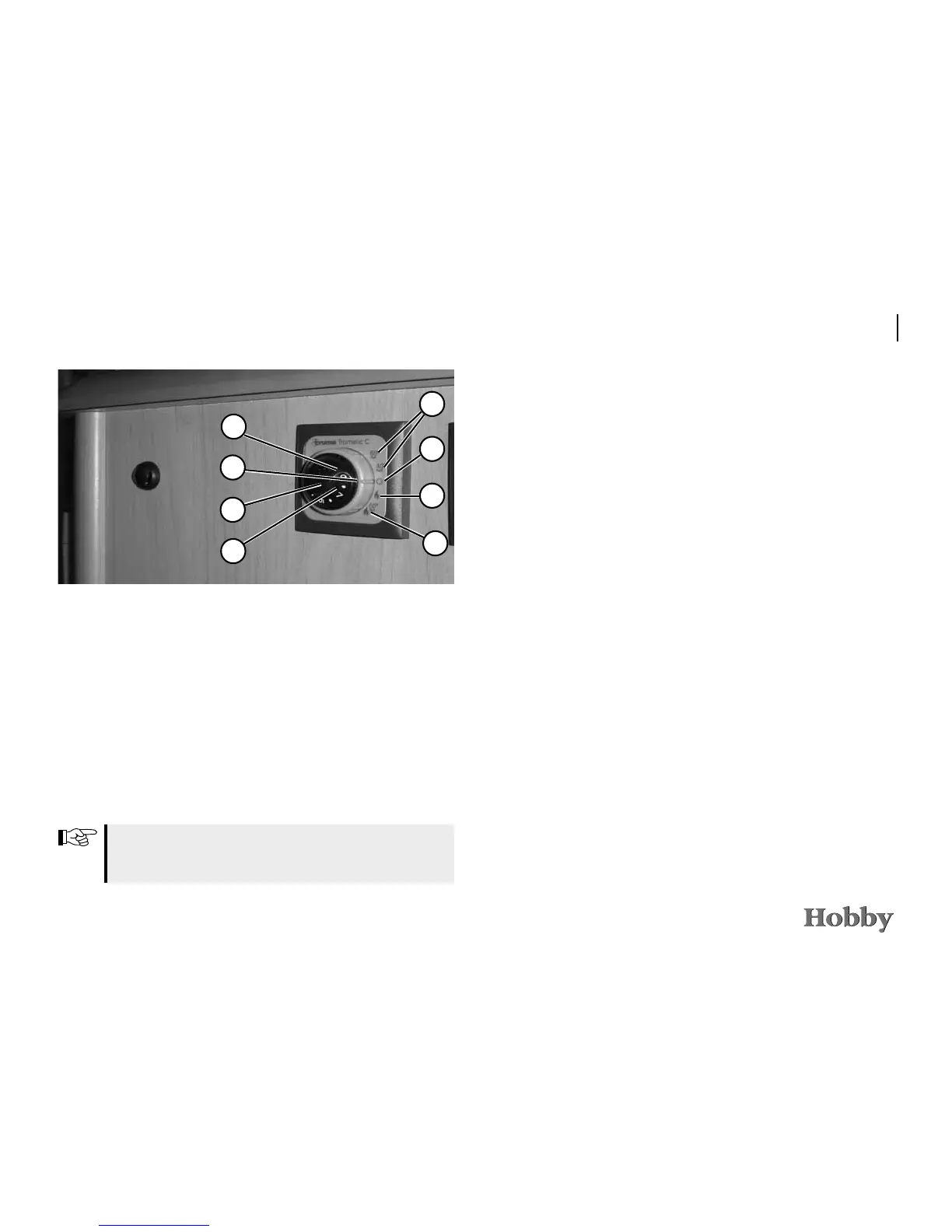
Gas operation (heating and warm water)
- Dial for room temperature (1)
- green “operating“ control light (2)
- summer operation (water temperature 40°C or 60°C (3)
- winter operation (heating without need for warm water) (4)
- winter operation (heating with need for warm water) (5)
- rotary switch “off“ (6)
- yellow control light: “boiler in heating phase“ (7)
- red control light: “malfunction“ (8)
For further information, please refer to the enclosed TRUMA
operating manual.
6.3 Electric power supply
Your mobile home has the following connections for electric
power supply:
- electric mains (a.c. voltage 230 V)
- caravan battery (d.c. voltage 12 V)
Electric power supply from the electric mains
The 230 V system is protected by a 2-pole circuit breaker with
16 A. The circuit breaker is located behind the driver‘s seat.
Should there be a malfunction, the passenger circuit breaker
opens the entire 230 V circuit. In most cases, such a malfunction
is caused by a defect piece of electric equipment or a defect
in its supply line.
• Repair the defect before switching the circuit breaker on
again.
• If the defect cannot be repaired, consult an experienced
electrician.
 Loading...