[71]
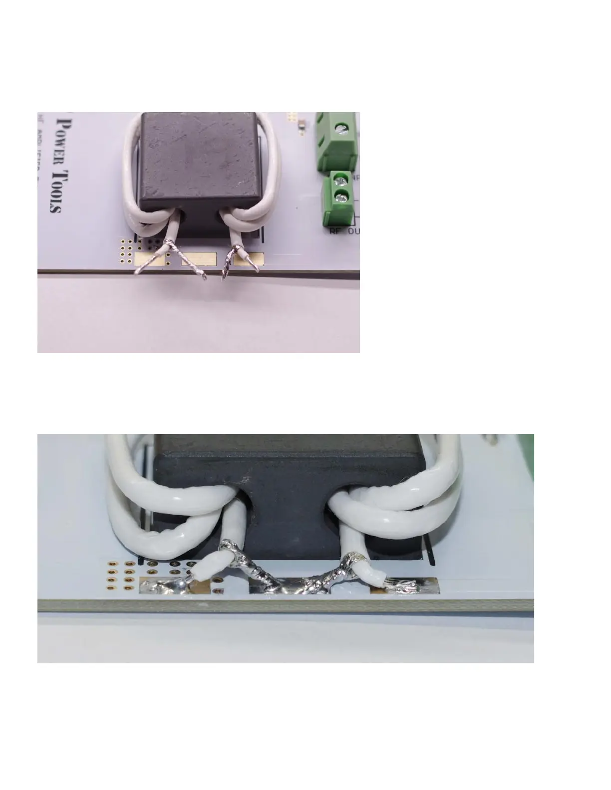
Strip the outer jacket of the protruding coax to approximately ¼” (6mm) from the core. Carefully unbraid the
shield wires and gather then towards the center of the three pads on the edge of the circuit board. Strip the
dielectric from the center conductors.
□Step 11: Complete T3 – Trim the wires and solder them to the pads. With each center conductor going to
one of the outer pads and both shields going to the center pad.
The shield of this coax is NOT at ground potential. Do not touch the shield while the unit is operating and do
not connect any portion of the shield to ground.


 To Next Page