EasyManua.ls Logo

Hoffman Controls 610 Series - Normal Operation

Default Icon
20 pages
Print Icon
To Next Page IconTo Next Page
To Previous Page IconTo Previous Page
Loading...
11
Model
610 Menu System
Flow Chart
Figure
8
5
.
Refer to
Figure
2
(page 4) to clamp three current transformers, one (1) current transformer
on each of the
power wires
(with all CTs facing the same way)
connected to the m
otor's
Starter
B
contactor's load side terminals
T1
,
T2
and
T3
.
6
.
Referring to
Figure
7
,
Dual Model 610 Part (Split) Winding Motor Wiring Diagram
(page
9),
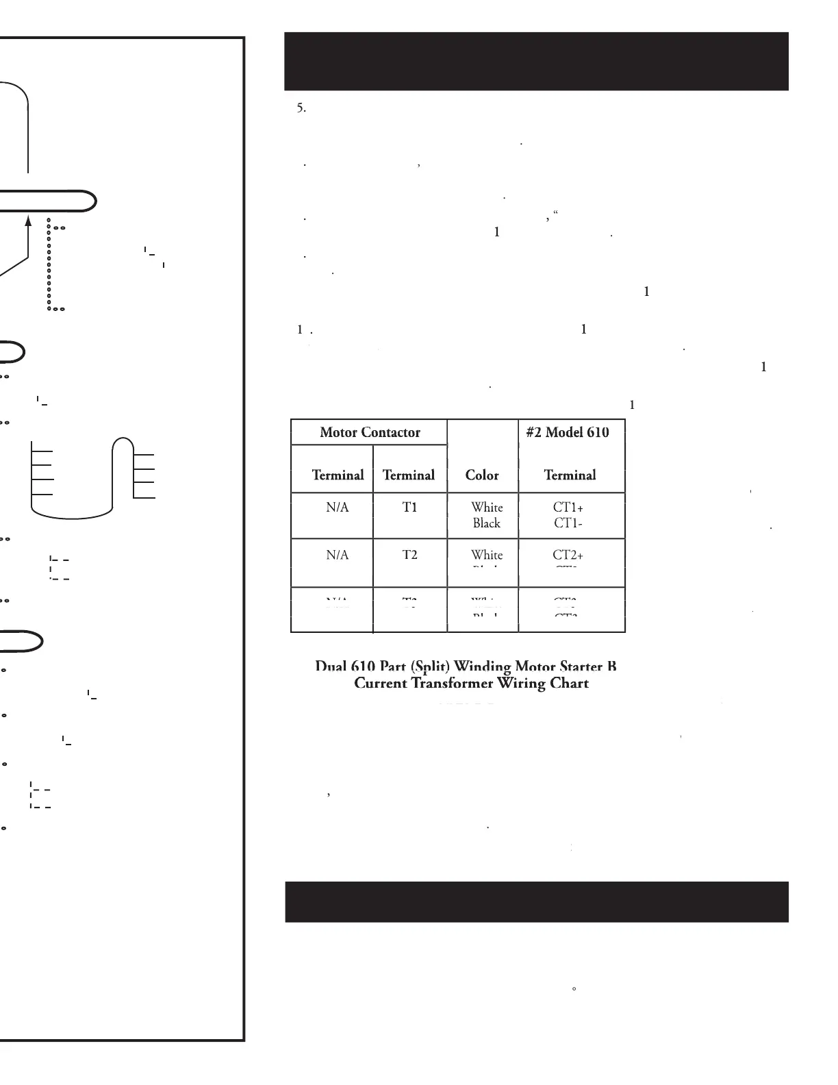
connect the current transformer's
wires to the
# 2
Model 610 Digital Current Monitor's CT
terminals
a
s shown in
TABLE 5
(
page
11
)
.
7
.
Connect 24 VAC power as show
n in
Figure
7
,
“
Dual
Model 6
10 Part (Split) Winding Motor
Wiring Diagram
” (page 9) to both the
#
1
and
#
2
Model 610's
.
8
.
C
onnect a
24 VAC source to
the
#
2
Model 610
TRIP
relay's
N.C.
terminal, as shown in
Figure
7
.
9
.
C
onnect
the
#
2
Model 610
TRIP
relay's
COM
terminal
to the
#
1
Model 610
TRIP
relay's
N.C.
terminal
, as shown in
Figure 7.
1
0
.
C
onnect
the
TRIP
relay's
COM
terminal, on the
#
1
Model 610,
to the 24
VAC side of
both
the
both the both
Starter A
and
Starter A and Starter A
Starter B
motor contactors' coils as shown in
Figure
7
.
11.
Verify the
Starter A
and
Starter A and Starter A
Starter B
motor contactors's coils are wired in parallel to the
#
1
Model 610
TRIP
relay's
COM
terminal
.
1
2
.
If an
alarm notification is
desired, refer to
Figure
7
and:
1. Connect the alarm's 24
VAC wire to the
N.O.
terminals
on
both
of
both of both
the
#1
and
#2
Model
610's
ALARM
relays
.
2
.
Connect the alarm's 24
VAC RTN wire to the
COM
terminals on
both
both both
of
the
#1
and
#2
Model
610's
ALARM
rela
ys.
relays. rela
3.
Verify the alarm's 24
VAC
wire
is connected
in
parallel to both
the
#1
and
#2
Model 610
ALARM
rela
y's
relay's rela
N.O.
terminals.
4
. Verify the alarm's 24 VAC RTN wire is connected in parallel to
both
the
both the both
#1
and
#2
Model 610
ALARM
relay's
COM
terminals.
13.
If compressor temperature sensing or Modbus RTU communication is desired,
refer to
Figure
9
,
Model 610 Exhaust Sensor, Oil Sensor and Modbus Wiring Diagram
(page 13)
and
the
Compressor Temperature Sensing Information
section (page 12)
and /or the
Mobus RTU
Installation
section (page 15)
for details
.
14.
This completes the
Dual 610 Part (Split) Winding
Motor
Dual 610 Part (Split) Winding MotorDual 610 Part (Split) Winding
's hard
ware installation. Continue
with the
Normal Operation
section below.
T
he controller will consistently display the Home Screen on the LCD showing the highest
phase's current, in amps, and the highest temperature in
°
F (when used). Also shown is the number
of trips that have been automatically reset since the last manual reset occurred, due to either an over
current condition or an abnormal temperature value, or a combination of the two.










































Normal Operation
During Current Monitoring
Dual 610, Part (Split) Winding Motor
Installation Con't
desired, refer to
and:
VAC wire to the
the
610's
VAC RTN wire to the
of
610's
and:
and:
Motor Contactor
desired, refer to
Motor Contactor
desired, refer to
and:
Motor Contactor
and:
Motor Contactor
desired, refer to
Motor Contactor
desired, refer to
and:
Motor Contactor
and:
Motor Contactor
desired, refer to
Motor Contactor
desired, refer to
and:
Motor Contactor
and:
#
desired, refer to
#
desired, refer to
and:
#
and:
2
desired, refer to
2
desired, refer to
and:
2
and:
Model 610
desired, refer to
Model 610
desired, refer to
and:
Model 610
and:
Starter A Starter B
CT Wire
PCB
Terminal Terminal
VAC wire to the
Terminal Terminal
VAC wire to the
Terminal Terminal
VAC wire to the
Terminal Terminal
VAC wire to the
Terminal Terminal
VAC wire to the
Terminal Terminal
VAC wire to the
Color
VAC wire to the
Color
VAC wire to the
Terminal
VAC wire to the
Terminal
VAC wire to the
Terminal
VAC wire to the
Terminal
VAC wire to the
Color TerminalColor
VAC wire to the
Color
VAC wire to the
Terminal
VAC wire to the
Color
VAC wire to the
VAC wire to the
VAC wire to the
the
the
N/A
the
N/A
the
the
the
the
N/A
the
the
N/A
the
T1
the
T1
the
White CT1+
the
White CT1+
the
White CT1+
the
White CT1+
the
White CT1+
the
White CT1+
the
Black CT1-
610's
Black CT1-
610's
Black CT1-
610's
Black CT1-
610's
Black CT1-
610's
Black CT1-
610's
Black CT1-
610's
Black CT1-
610's
VAC RTN wire to the
VAC RTN wire to the
N/A
N/A
VAC RTN wire to the
N/A
VAC RTN wire to the
VAC RTN wire to the
VAC RTN wire to the
T2
T2
VAC RTN wire to the
T2
VAC RTN wire to the
VAC RTN wire to the
VAC RTN wire to the
White CT2+
White CT2+
VAC RTN wire to the
White CT2+
VAC RTN wire to the
White CT2+
White CT2+
VAC RTN wire to the
White CT2+
VAC RTN wire to the
Black CT2-
VAC RTN wire to the
Black CT2-
VAC RTN wire to the
Black CT2-
VAC RTN wire to the
Black CT2-
VAC RTN wire to the
Black CT2-
VAC RTN wire to the
Black CT2-
VAC RTN wire to the
Black CT2-
VAC RTN wire to the
Black CT2-
VAC RTN wire to the
N/A
of
N/A
of
610's
N/A
610's
N/A N/A
T3
of
T3
of
610's
T3
610's
White CT
of
White CT
of
610's
White CT
610's
White CT
of
White CT
of
610's
White CT
610's
White CT
of
White CT
of
610's
White CT
610's
3+
of
3+
of
610's
3+
610's
Black CT3-
610's
Black CT3-
610's
Black CT3-
610's
Black CT3-
610's
Black CT3-
610's
Black CT3-
610's
Black CT3-
610's
Black CT3-
610's
VAC wire to the
Starter A Starter B
Terminal Terminal
VAC wire to the
Terminal Terminal
VAC wire to the
the
the
610's
the
the
Black CT1-
610's
Black CT1-
610's
VAC RTN wire to the
VAC RTN wire to the
VAC RTN wire to the
Black CT2-
VAC RTN wire to the
Black CT2-
VAC RTN wire to the
of
610's
Black CT3-
610's
Black CT3-
610's
desired, refer to
and:
VAC wire to the
Motor Contactor
desired, refer to
Motor Contactor
desired, refer to
and:
Motor Contactor
and:
Starter A Starter B
Terminal Terminal
VAC wire to the
Terminal Terminal
VAC wire to the
the
610's
White CT1+
the
White CT1+
the
Black CT1-
610's
Black CT1-
610's
VAC RTN wire to the
VAC RTN wire to the
VAC RTN wire to the
Black CT2-
VAC RTN wire to the
Black CT2-
VAC RTN wire to the
of
610's
White CT
of
White CT
of
610's
White CT
610's
Black CT3-
610's
Black CT3-
610's
desired, refer to
and:
VAC wire to the
desired, refer to
Motor Contactor
desired, refer to
Motor Contactor
desired, refer to
and:
Motor Contactor
and:
CT Wire
Terminal
VAC wire to the
Terminal
VAC wire to the
the
610's
White CT1+
the
White CT1+
the
Black CT1-
610's
Black CT1-
610's
VAC RTN wire to the
White CT2+
White CT2+
VAC RTN wire to the
White CT2+
VAC RTN wire to the
Black CT2-
VAC RTN wire to the
Black CT2-
VAC RTN wire to the
of
610's
White CT
of
White CT
of
610's
White CT
610's
Black CT3-
610's
Black CT3-
610's
Dual 610 Part (Split) Winding Motor Starter
in
Dual 610 Part (Split) Winding Motor Starter
in
B
in
B
in
Current Transformer
and
Current Transformer
and
Wiring Chart
and
Wiring Chart
and
TABLE 5
TABLE 5

Related product manuals