Select the phase imbalance delay time.
Select the type of exhaust and / or oil temperature sensors used
Select the number of automatic trip resets before lockout
Select the delay time between automatic reset attempts.
Select when an external alarm should be activated.
Select the Modbus RTU settings.
Restore the control to factory default settings.
During normal operation, all the Model 610 Monitors' LCDs
display a Home Screen which shows the following information:
The present amp draw from the load's phase that is car-
rying the highest current.
The present highest sensed temperature value. When both the
sensors are activated, only the sensor that has
the highest temperature is displayed on the Home Screen.
The number of automatically reset trips allowed before a
The number of automatically reset trips that have occurred
button during normal operation, the
LCD will display, in real time, all three phase currents in amps, and
(installed) or have not been selected
. The unused phase currents and
temperature sensor values are displayed as "
button during normal operation, the LCD
will display the following information about the last trip that
The trip type (current, phase imbalance, temp high, temp low,
The value that caused the trip, and the time in hours since the
last trip occurred (up to 32,000 Hrs.).
The stored current values, for all three phases, that caused a
phase imbalance during motor startup.
During a tripped condition, the LCD will display “
If the trip has resulted in a lockout, then “
” will be displayed on the LCD.
All the Model 610's have an automatic time out that returns the
LCD to the Home Screen whenever the control's push buttons have
not been pressed for more then 5 minutes. If the time out occurs
before any menu changes have been saved (by pressing the
button), the unsaved changes will be ignored.
LCD Screens After UP Button is Pressed
The Model 610 Digital Current Monitor can be used for local,
remote or a combination of both local and remote operation.
The Model 610 Digital Current Monitor can be operated manu-
ally using the four (4) push buttons and LCD screen. The push
NTER) allow the installer to NTER
use the LCD's menu system to select the desired mode and then
set the available options, parameters and numerical values associ-
ated with that particular mode.
The Model 610 Digital Current Monitor has six (6) modes with
each mode containing the specific menus
and numerical value selections needed to implement that mode's
The LCD display routinely shows a Home Screen.
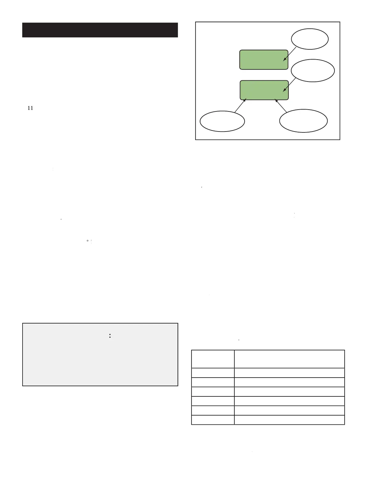
odify the Model 610's operation by
button, a specific number of times, to
MODE button, a specific number of times, to MODE
. After that mode's selected parameters and numeric values
updated, the Model 610's LCD automati-
cally returns to the Home Screen. To continue viewing or updating
another mode's parameters, the installer needs to press the
button the required number of times to enter that mode, as shown
Temperature Trip settings
Trip Auto Reset and Alarm
Reset Controller (to factory settings)
Number of Mode Button Presses
button when one of the above modes
ENTER button when one of the above modes ENTER
is displayed on the LCD's screen, the operator enters that mode's
menus and submenus where specific actions can be taken and
Description Con't
Local (Manual) Operation:
During Local (Manual) Operation:During
The "HrAgo" (Hours Ago) text, located next to the LCD
screen's right edge, gradually slides off the screen one
letter at a time as the displayed number of hours since
the last trip becomes so large that there is no room for
the "HrAgo" text to remain on the screen.
 Loading...