Do you have a question about the Hoffman geodyna 6300-2 and is the answer not in the manual?
Explains special symbols and text highlighting used for better understanding of instructions and images.
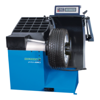
Describes the intended use and application scope of the wheel balancer for cars and light trucks.
Instructions for safe and proper unpacking of the machine by two persons.
Guidelines for safely moving the machine to a new location using appropriate equipment.
Overview of the machine's keyboard and display panel, including symbols and functions.
Factory default settings and operational modes available after machine power-on.
Lists common error codes encountered during machine startup and how to acknowledge them.
Instructions for mounting the wheel adaptor onto the machine's main shaft for wheel clamping.
Procedure for performing a compensation run to balance clamping means and ensure accuracy.
Guidelines for clamping car and light-truck wheels using appropriate adaptors.
Procedure for manually selecting vehicle type using function keys and wheel rotation.
Explains how to select balancing modes based on wheel type and weight fitting positions.
Procedure for entering wheel dimensions for standard balancing mode.
Automatic measurement and entry of distance and diameter using the Geodata gauge arm.
Procedure for entering balance clip data, including manual adjustments.
Procedure for manually reading and entering the wheel diameter.
Checking for wheel run-out before actual measurement to ensure proper tire mounting.
Automatic recognition of ALU type and weight positions using the Easy Alu function.
Procedure for starting measurement, displaying unbalance, and identifying correction positions.
Step-by-step guide for fitting balance weights for all balancing modes.
Procedure for performing a check run after balance weights are fitted to verify correctness.
Procedure for measuring and correcting static unbalance, especially for small or narrow wheels.
Steps for activating and using the behind-the-spokes placement mode.
Selection of balancing mode and input of wheel data for behind-the-spokes placement.
Procedure for correcting measured unbalance in behind-the-spokes placement mode.
Explains how to input codes to change operating modes and view settings.
Selects a previously stored wheel profile.
Stores the current wheel settings as a wheel profile.
Displays program version and model number.
Selects error codes from memory for review or clears the error memory.
Lists error codes related to operational mistakes or incorrect inputs.
Lists warning codes indicating potential issues or non-critical errors.
Lists critical error codes indicating serious malfunctions or failures.
Explains optimisation and weight minimisation procedures for improving wheel running conditions.
Provides guidance on using the optimisation and minimisation programs, including interruption and continuation.
Detailed steps for the optimisation program, including tyre rotation and valve position entry.
Detailed steps for the weight minimisation program, including tyre adjustment and data entry.
Instructions for replacing the halogen lamp used for inner rim illumination.
| Brand | Hoffman |
|---|---|
| Model | geodyna 6300-2 |
| Category | Wheel Balancers |
| Language | English |