Do you have a question about the Hoffrichter CARAT I and is the answer not in the manual?
Denotes hazardous situations that can lead to serious injuries or death.
Denotes hazardous situations that may lead to serious injuries or death.
Denotes information, tips, and instructions for efficient, error-free device use.
Procedure for device reprocessing by qualified personnel, involving disposal, autoclaving, and disinfection steps.
Hygienic reprocessing according to KR 1000 procedure with limited cycles, followed by a safety test.
Procedure for reprocessing when using a bacteria filter, including filter changes and disinfection.
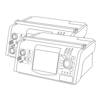
Diagram detailing pneumatic components and signal flow paths for the CARAT I model.
Diagram detailing pneumatic components and signal flow paths for the CARAT II model.
Shows the overall system architecture including ventilator, power, and controller modules.
Details the functional blocks and interfaces of the controller circuit board.
Outlines the power management system, including battery charging and distribution circuits.
Describes the functions and sections of the main control circuit board.
Procedures for cleaning and disinfecting the device covers and air-ducting components.
Details steps for calibrating the pressure sensor using an APM device and specific menu functions.
Outlines the process for calibrating the flow sensor using a flow meter and service menu.
Procedure to test for leaks in the system by monitoring pressure changes during operation.
States that the respiratory machine requires annual servicing by an authorized specialist.
Provides a schedule for required maintenance tasks based on operating hours or time intervals.
| CPAP Pressure | 4 - 20 cmH2O |
|---|---|
| Ramp Function | Yes |
| Weight | 1.8 kg |
| Humidifier | Optional |
| Data Storage | SD card |
| Operating Mode | CPAP |
| Sound Level | < 26 dB(A) |
| Noise level | < 26 dB(A) |