8 List of figures
List of figures
Figure 1: Rating plate ............................................................................... 12
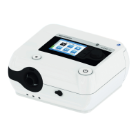
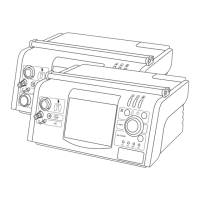
Figure 2: Front side of device ................................................................... 28
Figure 3: Rear of device ........................................................................... 28
Figure 4: Left device side .......................................................................... 28
Figure 5: Bottom of device ....................................................................... 29
Figure 6: Top of device ............................................................................. 29
Figure 7: Setting up the device ................................................................. 34
Figure 8: Assembling the power supply unit and power supply unit holder 35
Figure 9: Mains connection via power supply unit ..................................... 36
Figure 10: Start screen ............................................................................... 37
Figure 11: System setup, non-invasive ventilation with vented mask ............ 41
Figure 12: System setup, non-invasive ventilation with non-vented mask ..... 41
Figure 13: System setup, invasive ventilation with external humidifier .......... 43
Figure 14: System setup, invasive ventilation with HME filter ....................... 44
Figure 15: Inserting the SD card ................................................................. 47
Figure 16: Removing SD card ..................................................................... 48
Figure 17: Functional bag........................................................................... 49
Figure 18: Home screen ............................................................................. 56
Figure 19: Measurement screen, factory setting .......................................... 58
Figure 20: Graph screen ............................................................................. 58
Figure 21: Parameter screen ....................................................................... 59
Figure 22: Event log screen (alarms) ........................................................... 61
Figure 23: Event log screen (events)............................................................ 61
Figure 24: System screen ............................................................................ 62
Figure 25: Statistics screen ......................................................................... 64
Figure 26: Alarm displays on the toolbar .................................................... 67
Figure 27: Alarm output on the toolbar ...................................................... 68
Figure 28: Messages on the toolbar ........................................................... 74
Figure 29: Filter cassette structure .............................................................. 79
Figure 30: Error list .................................................................................... 87