Hog Slat Inc. Newton Grove, NC USA June 2017
Installation:
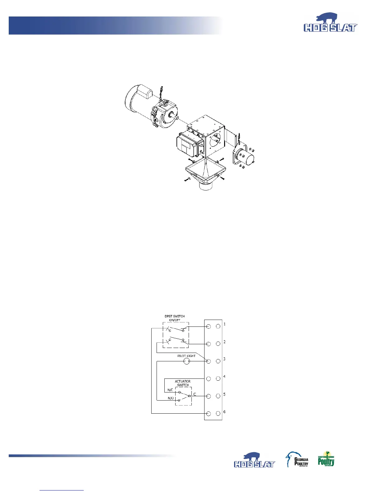
1. (Figure 1) illustrates a typical installation example of the HS593 control unit.
a. Mount tube anchor to one side using (4) 5/16” x ¾” bolts with (4) flat washers.
b. Mount auger power drive unit gear box secured with (4) 5/16” x ¾” bolts and (4) flat washers.
FIGURE 1
2. The HS593 Control Unit must be hardwired. See (Figure 2) for factory wiring diagram.
3. See below Figures 3 and 4 for external wiring for single phase and three phase operation.
4. When connecting wire from equipment to terminal strip, remove no more than ¼” of insulation from end of wire.
Be sure there are no stray wire strands before inserting wire into terminal strip. Insert wire into terminal ¼” and
tighten terminal strip set screw.
5. When using Hopper Level Control Switch, switch should be wired as “Normally Closed” contact.
6. If No Hopper Level Control Switch is to be used, Place jumper wire between terminals (5) and (6).
7. Use provided self-tapping screws to provide bonding to Control Unit Switch Assembly and other
connected equipment.
8. Pilot indentions are provided and located to allow for sufficient clearance for ½” non-metallic liquid tight strain relief
cord connectors. DO NOT USE RIGID CONDUIT.
9. Care should be taken when drilling pilot holes to prevent damage to wires or other components.
FIGURE 2
 Loading...