EasyManua.ls Logo

HOGG & DAVIS HYDRA 985 User Manual

HOGG & DAVIS HYDRA 985
114 pages
To Next Page IconTo Next Page
Page #1 background imageLoading...
Page #1 background image
HYDRA 985
The information, specifications, and illustrations in this manual are on the basis of
information available at the time it was written. The specifications, torque values,
pressures of operation, measurements, adjustments, illustrations, and other
items can change at any time. These changes can affect the service of the given
product.
For the complete and most current information, contact:
Hogg & Davis, Inc
P.O. Box 405 / 3800 Eagle Loop
Odell, OR 97044-0405
541-354-1001
541-354-1080 Fax
For most recent manual
version please visit:
www.hoggdavis.com
Question and Answer IconNeed help?

Do you have a question about the HOGG & DAVIS HYDRA 985 and is the answer not in the manual?

HOGG & DAVIS HYDRA 985 Specifications

General IconGeneral
BrandHOGG & DAVIS
ModelHYDRA 985
CategoryConstruction Equipment
LanguageEnglish

Summary

PRODUCT WARNINGS

OPERATIONS

INTRODUCTION

GENERAL SPECIFICATIONS

DIESEL ENGINE SPECIFICATIONS

TRAILER ORIENTATION

A. MAIN FRAME AND AXLE

Details the primary structural component of the trailer.

B. POWER UNIT

Describes the engine and its housing.

C. POWER IDLER WHEEL AND CONTROLS

Explains the idler wheel and its controls.

D. REEL CARRYING RACKS

Covers the components for holding reels.

MAIN FRAME AND AXLE

CONTROLS

A. Hydrastatic Pressure Gauge

Gauge indicating system pressure during operation.

B. Front / Rear Control

Switch to isolate front and rear controls.

C. Ignition Switch

Switch for starting and stopping the unit.

D. Switch Panel

Panel with various switches for unit functions.

E. Joystick

Control for payout/take-up, with proportional speed.

LOADING INSTRUCTIONS

HYDRAULIC CONTROLS

Power Unit Features

Highlights key features of the power unit.

FRONT HYDRAULIC CONTROLS

A - STEER GO SYSTEM

System for steering the trailer.

FRONT CONTROL BANK

A - DRAWBAR RAISE AND LOWER

Controls for adjusting the drawbar height.

B - POWER UNIT FORWARD AND BACK

Controls for moving the power unit.

POWER UNIT

AUXILIARY POWER SHAFT

POWERED IDLER WHEELS AND HYDRAULIC CONTROLS

REEL CARRYING RACKS (MANDREL RACKS)

JACKSTANDS

MANUERVERING INSTRUCTIONS

STEER-GO OPERATION

THE JOYSTICK

TO STEER AND MOVE

BRAKE CONTROLLERS

ON BOARD AIR COMPRESSOR

TOOL CIRCUIT (OPTIONAL)

LEVELWIND OPERATIONS

LEVELWIND COMPONENTS

PULLING PROCEDURES

OVERHEAD WIRE

Step-by-step guide for overhead wire pulling.

UNDERGROUND PULLING

SERVICE

HYDRA 985 Lubrication

JACKSTAND INSTALLATION

DRIVE ROLLER MAINTENANCE

ACME ADJUSTING SCREW

DRAWDAR INSPECTION

MANDREL RACK STABILIZER INSTALLATION

Vehicle Specification

Optional Equipment

Fail Safe Brake

Description of the dual caliper brake system.

Tool Circuit

Auxiliary hydraulic circuit for light duty tool use.

Hydraulic Outriggers

Hydraulic operated rear stabilizers.

Levelwind System

Optional levelwind for winding cable onto drums.

Auxiliary Capstan

Optional capstan on street side rear fender.

Hub Torque Specifications

HUBS (For Ball Seat Mounted Disc Wheels)

Torque specs for ball seat mounted disc wheels.

HUBS (For Pilot Mounted Disc Wheels)

Torque specs for pilot mounted disc wheels.

Wheel Torque Specifications

SPOKE WHEELS

Torque specs for spoke wheels.

BRAKE DRUM OR ROTOR ASSEMBLY TORQUE SPECIFICATIONS

Torque specs for brake drum or rotor assembly.
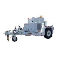
HYDRA 985 Decals

Decal Locations

Decal Locations

Decal Locations