EasyManua.ls Logo

HOKUYO AUTOMATIC UBG-05LN - User Manual

HOKUYO AUTOMATIC UBG-05LN
17 pages
Print Icon
To Next Page IconTo Next Page
Loading...
HOKUYO AUTOMATIC CO.,LTD.
Sep.5th'06
Be sure to read this instruction manual carefully before using to make correct operation of this device.
Be sure to read this instruction manual and keep properly.
Symbol Amended reason Pages Date Corrector Amended No.
Approved by Checked by Drawn by Designed by
Title
Measuring Distance Type Obstacle Detection
Sensor UBG-05LN Instruction Manual
MORI
Drawing
No.
C-41-2384 1/17
MEASURING DISTANCE TYPE
OBSTACLE DETECTION SENSOR
UBG-05LN
INSTRUCTION MANUAL
Question and Answer IconNeed help?

Do you have a question about the HOKUYO AUTOMATIC UBG-05LN and is the answer not in the manual?

Overview

Measuring Distance Type Obstacle Detection Sensor UBG-05LN Instruction Manual

This document provides comprehensive instructions for the safe and effective use, installation, and maintenance of the HOKUYO Measuring Distance Type Obstacle Detection Sensor UBG-05LN. It is crucial for all operators and maintenance personnel to read this manual thoroughly and keep it accessible for reference. Adherence to these guidelines ensures correct operation, prevents malfunctions, and promotes safety.

General Function Description

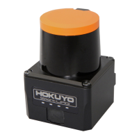
The UBG-05LN is an obstacle detection sensor that utilizes a 785nm wavelength laser light source to detect objects within a predefined area. It operates by scanning a 180° semicircle, measuring the distance and angle to detected objects, and calculating their coordinates. This product is classified as laser class 1, ensuring its safety under ordinary operating conditions.

Usage Features

Detecting Area Setting: The device allows for flexible configuration of its detecting area. Users can define the shape and setting values of the detection area using PC software via a serial input/output connection. This enables precise customization to suit various application environments.

Detecting Area Pattern Changeover: The UBG-05LN supports up to 15 different detecting area patterns, which can be pre-set using PC software. These patterns can then be switched dynamically via outer bit input, offering adaptability to changing operational requirements.

Output Signals: The sensor provides three steps of output for each detecting area, indicating the presence of an obstacle at different distances. Additionally, it includes a "Trouble output" function that activates during normal operation but turns OFF if a trouble condition is detected.

Emission Stop Function: For applications where the Automatic Guided Vehicle (AGV) is stationary, an emission-stop function is available. This feature suspends the emission of the LED when all input signals (1 to 5) are set to ON (L level), preventing interference with other sensors or systems. It's important to note that rebooting after releasing the emission-stop input takes approximately 1 second.

Hysteresis Changeover: The device allows for hysteresis adjustment, which is particularly useful when the detecting area is set near a wall. By making the hysteresis smaller, the sensor can prevent false detections of the wall surface after an AGV or human has passed through the detecting area, ensuring smooth operation.

Self-Diagnosis Function: The UBG-05LN incorporates a self-diagnosis function that monitors for issues such as LED emission trouble or motor revolution trouble. In the event of such a problem, the device will activate its trouble output, and the power lamp will flicker at 1-second intervals, alerting operators to a potential issue.

Response Time: The input taking-in cycle is 1 scanning time (100ms or 110ms). However, when the detecting area is changed by outer input, the response time will be slower, with an additional changeover time of approximately 100ms. If emission stop is selected by external input, the input taking-in cycle is 1msec.

Maintenance Features

Cleaning: Regular cleaning of the lens surface for both the light-projecting and receiving parts is essential. This should be done periodically with a soft cloth. A dirty lens can impair the sensor's ability to maintain its specific detection area, potentially leading to mis-operation.

Installation Guidelines: Proper installation is critical for optimal performance and to prevent malfunctions.

  • Cover Relation: The UBG-05LN should be installed so that it extends 30mm or more out from any cover. If the distance is 30mm or less, the sensor may detect shorter than the actual distance. In such cases, the detecting area view angle should be shortened, or black seals should be applied to both sides of the UBG to prevent cover detection.
  • Clearance: It is crucial not to obstruct the light-projection/reception window or interrupt the detection area during installation.
  • Cover Transparency: If a cover is used, it must be highly transparent, as the sensor uses a diode with a wavelength of 785nm.
  • Floor Surface Relation: The sensor beam has a diameter of approximately 100mm at 3m. If installed near the floor surface, it may detect the floor and cause malfunctions. To avoid this, install it 60mm or more away from the floor, or if 60mm or less, install it 1 degree upward.
  • Firm Installation: The device must be installed firmly to prevent dislocation of the optical axis due to vibration or impact.
  • Optical Axis Adjustment: For precise detection of objects 300mm x 300mm or larger, it is possible to align the up/down angle with the mechanical axis. An adjusting mechanism may be necessary for severe adjustments. The dispersion of the optical axis against the mechanical axis is typically ±0.3° horizontally and ±1° up/down. An optical axis adjustment should be performed, and operations checked before use.

Environmental Considerations:

  • Power Source: Use a power source with 1.5A or more current capacity. An inrush current of 300mA flows when the power source is initially applied. The voltage range, including ripple, is 18 to 30VDC.
  • Strong Light Avoidance: Avoid installing the sensor in locations where strong light exceeding rated levels enters the reception part, as this can cause mis-operation.
  • Wiring: Do not make wiring with power lines such as driven motors or breaks, as this can cause malfunction or mis-detection due to electric noise.
  • Grounding: Earth the frame ground terminal to the body when a switching regulator is used as the power source.
  • Unused Cables: Connect unused input cables to input common +(Red) or leave them open. Similarly, connect unused output cables to output common –(Gray) or leave them open.
  • RS-232C Connection: Do not connect any other cable to the RS232C signal cable except when setting the detecting area via PC. Ensure unused pins (RTS-CTS-CD and DTR-DSR) are short-circuited. Use a cable within 3m between the UBG and the PC for detecting area settings.

Troubleshooting: In case of incorrect operation, stop using the device and investigate the cause. If the problem cannot be identified, contact the branch office for assistance. Common issues and their solutions include:

  • Power lamp not lighting up: Check wiring and power source.
  • Inability to change detecting output: Check I/O wiring, installation, detecting area settings, and hysteresis.
  • Flickering power lamp: This indicates a trouble condition within the UBG, and the device may need to be replaced.

Long-Term Use: For applications requiring absolute precision over a period of one year or more, periodic correction of the sensor may be necessary to maintain accuracy.

Limitations:

  • The sensor cannot detect a dead space of view within its beam scanning angle (0.1m from the scanning center). If the necessary detecting area is not sufficient, the device should not be used.
  • The device may cause malfunction or mis-detection due to strong disturbance light, electric noise, or mechanical vibration.
  • It cannot stably detect retro-reflectors.
  • If the reflectance of an object is extremely low (e.g., mourning dress or oil-stained clothes), it may be impossible to measure even within 1m.
  • Mutual interference can occur if multiple UBG sensors are used in close proximity, potentially delaying response time. In such cases, an angle of elevation of 2° or more is recommended.
  • Avoid using the device under solvent vapor and corrosive gas.
  • Do not decompose the device, as this may cause short-circuit troubles, malfunctions, and void the warranty.
  • Keep the device away from water, oil, or scales, as these can reduce light-receiving amount, cause mis-detection, and corrode inner circuits.
  • Do not install or store the device in places with over-rated heat, vibration, or shock, as this can cause troubles or malfunctions.

This instruction manual serves as a vital resource for ensuring the safe, efficient, and reliable operation of the UBG-05LN sensor. By adhering to these guidelines, users can maximize the device's performance and longevity.

HOKUYO AUTOMATIC UBG-05LN Specifications

General IconGeneral
Distance range0.06 to 5.6 m
Accuracy±30 mm
Angular resolution0.36° (360°/1024 steps)
InterfaceUSB, RS-232C
Operating temperature0 to 40°C
WeightApprox. 300 g
Protection classIP65
Resolution1 mm
Light sourceLaser diode
Laser safety standardIEC Class 1
Shock resistance196 m/s2, 10 times each in X, Y, and Z directions
Scan Time25 ms/scan
Power Supply12 VDC ±10%
Scanning angle190 degrees
Power supply voltage12 VDC ±10%

Related product manuals