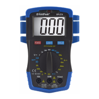
HP-37A
DIGITAL MULTIMETER
OPERATOR’S MANUAL
1. Overview
The multimeter is characterized at slim size, portable, stable performance
and anti-dropping capacity. Using 3 1/2 digits LCD monitor with character
28mm high, they offer clear readings. With overall circuitry design
centering on large-scale IC
/D converters in conjunction and over-load
protection circuit, the meters give excellent performance and exquisite
making as a handy utility instrument.
The meters can be used to measure DC &
C voltage, DC current,
resistance, temperature, battery test, positive diode voltage fall and
audible continuit
.
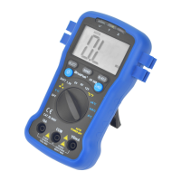
2. Panel Layout
1
Test lead fixture: Fix the test lead.
2
LCD display: 3 1/2 digits LCD display.
3
HOLD key: Press the “HOLD” key to lock display value, and the “DH”
sign will appear on the display , press it again to exit.
4
LIGHT key: Press the “LIGHT” key to light up the LCD backlight,
press it again to exit, it will be automatically turned off too after
approx. 30 seconds. If the battery is in weak power, the light will be
dimmed. Press the key to power on when auto power off.
5
Rotary Switch: Use this switch to select functions and ranges.
6
COM: COM and Temperature “
8
VΩmA: V/mA/BATT/ and Temperature “+” Input Jac
9
Crust of meter
10
Protective casing
3. Safety Information
3-1 The meter is designed according to IEC-1010 concerning electronic
measuring instruments with an over-voltage category 600
(CAT Ⅲ)and
pollution 2.
3-2 Follow all safety and operating instructions to ensure that the meter is
used safely and is kept in good operating condition.
3-3 safety symbols:
Important safety information, refer to the operating manual.
Dangerous voltage may be presence.
Double insulation (protection Class II)
4. Special Cautions fo
Operation
4-1 The meters can be safe only according to standard procedures when
used in conjunctions with the supplied test leads. To replace damaged test
leads with only the same model or same electric specifications.
4-2 To avid ris
of electric shock, do not use the meters before the cover is
in place.
4-3 The range switch should be right position for the testing.
4-4 To avoid electric shoc
and damaging the instruments, the input
signals are forbidden to exceed the specified limits.
4-5 When measuring TV set or switched powe r, attention should be paid to
the possible pulses that may bring destruction to the circuit.
4-6 Range switch position is forbidden to be changed at random during
measurement.
4-7 Take caution against shock in the course of measuring voltage higher
than DC 60V &
C30V.
4-8 Protection fuse should be replaced only with same type and same
specification.
4-9
fter operation is finished, set function switch at OFF range to save
battery power.
4-10 If the meter is without usage for long time, take out battery to avoid
damage by battery leakage.
5. GENERAL SPECIFICATIONS
5-1 Max Voltage between input terminal and Earth Ground: CAT Ⅲ 600V
5-2 Over-range Indication: display “1” or “-1” for the significant digit.
5-3
utomatic display of negative polarity “-” .
5-4 Low Battery Indication: “
” displayed.
5-5 Display: 3 1/2 digit LCD with a max. reading of 1999.
5-6 Manual range control
5-7
uto Power Off: The meter will switch to standby mode when power on
after approx. 30 minutes. Press the LIGHT key or rotate the rotary
switch to OFF position, then power on to exit standby mode.
5-8 Fuse protection: 200mA/250V PPTC Resettable Fuse
5-9 Power supply: 9V battery (6F22 or NED
1604)
5-10 Operating Temp.: 0℃ to 40℃ (relative humidity <85%)
5-11 Storage Temp.:-10℃ to 50℃ ((relative humidity <85%)
5-12 Guaranteed precision Temp.: 23±5℃ (relative humidity <70%)
5-13 Dimension: 150x106x36mm
5-14 Weight: approx. 250g (including battery)
6. Testing Specifications
ccuracy is specified for a period of year after calibration and at 18℃ to
28℃ (64℉ to 82℉) with relative humidity to 70%.
6-1 DC
oltage
Range Resolution Accuracy
2V 1mV
±(0.5% of rdg + 2 digits)
20V 10mV
200V 100mV
600V 1V ±(0.8% of rdg + 2 digits)
-- Impedance: 1MΩ
-- Overload protection: 600V DC or
oltage
Range Resolution Accuracy
200V 100mV
±(1.5%ofrdg+5digits)
600V 1V
-- Impedance: 450
Ω
-- Overload protection: 600V DC or
Crms
-- Frequency Range: 40 to 400Hz
-- Response: average, calibrated in rms of sine wave
6-3 DC Current
Range Resolution Accuracy
2mA 1μA
±(1.2% of rdg + 2 digits)20mA 10μA
200mA 100μA
10A 10mA ±(2.0% of rdg + 3 digits)
-- Overload protection: 200mA/250V PPTC Resettable Fuse
Note: 10
up to 10 seconds
6-4 Resistance
Range Resolution Accuracy
200Ω 0.1Ω ±(1.0% of rdg + 3 digits)
2kΩ 1Ω
±(1.0% of rdg + 2 digits)20kΩ 10Ω
200kΩ 100Ω
2MΩ 1kΩ ±(1.5% of rdg + 3 digits)
-- Overload protection: 250
Crms
6-5 Temperature
Range Accuracy Resolution
℃
-20~150℃ ±(3℃+ 1digit )
1℃
150~1000℃ ± ( 3% of rdg + 2digits )
-- NiCr-NiSi K-type sensor
-- Overload protection: 200mA/250V PPTC Resettable Fuse
6-6 Battery test
Range
ccuracy Load current Resolution
±(5.0% of rdg + 5 digits)
pprox. 10mA 10mV
-- Overload protection: 200mA/250V PPTC Resettable Fuse
6-7 Diode and
udible continuity test
Range Description Test Condition
Display read approximately
forward voltage of diode
Forward DC current
approx. 1m
Reversed DC voltage
approx. 3V
Built-in buzzer sounds if
resistance is less than 50Ω
Open circuit voltage
approx. 3V
Overload protection: 250V DC or