EasyManua.ls Logo

HoldPeak 39K User Manual

HoldPeak 39K
2 pages
To Next Page IconTo Next Page
Page #1 background imageLoading...
Page #1 background image
39K
DIGITAL MULTIMETER
OPERATOR’S MANUAL
1. Overview
The multimeter is characterized at slim size, portable, stable performance and
anti-dropping capacity. Using 4000 counts digit LCD monitor with character
25mm high, they offer clear readings. With overall circuitry design centering on
large-scale IC A/D converters in conjunction and over-load protection circuit, the
meters give excellent performance and exquisite making as a handy utility
instrument.
The meters can be used to measure DC & AC voltage, DC & AC current,
resistance, capacitor, frequency, duty cycle, Non Contact AC Voltage (NCV)
detection, positive diode voltage fall and audible continuity.
2. Panel Layout
1. Test lead fixture: Fix the test lead.
2. CDS sensor: The CDS sensor can reaction to the ambient brightness range,
then automatically control the LCD backlight to lighten or go out.
3. NCV detection area: Non Contact AC Voltage (NCV) detection area.
4. NCV red light: Non Contact AC Voltage (NCV) detection red light.
5. NCV green light: Non Contact AC Voltage (NCV) detection green light.
6. LCD display: 4000 counts digit, full function symbol display.
7. SELECT key: This key work on the " " range, press the key to choose
diode or continuity test, on the current range, change to DC or AC; If press and
hold SELECT key to power on, “Auto Power Off ” function will be disabled.
8. NCV Key: Press and hold the NCVkey, the meter enters Non Contact AC
Voltage (NCV) detection, the NCV green LED light will light up, free it to exit.
9. HOLD key: Press the HOLD” key to lock display value, and the DH” sign will
appear on the display, press it again to exit.
10. REL Key: Press the RELkey, the meter enters relative measuring mode,
RELis displayed on the LCD and the present reading becomes the reference
value and displayed on the display. Relative measurement REL=measurement
value-Reference value. Press it again to exit.
11. Hz/% Key: On “ACV/ACA” or “Hz” range, press the Hz/% key, you can
choose the Frequency or Duty Cycle measurement.
12. Rotary Switch: Use this switch to select functions and ranges.
13. COM: COM Input Jack
14. 10A: 10A Input Jack
15. VΩmA: V/μAmA/Hz/ Input Jack
16. Crust of meter
17.Protective casing
3. Safety Information
3-1 The meter is designed according to IEC-1010 concerning electronic
measuring instruments with an over-voltage category 600V (CAT) and
pollution 2.
3-2 Follow all safety and operating instructions to ensure that the meter is used
safely and is kept in good operating condition.
3-3 safety symbols:
Important safety information, refer to the operating manual.
Dangerous voltage may be presence.
Double insulation (protection Class II)
4. Special Cautions for Operation
4-1 The meters can be safe only according to standard procedures when used in
conjunctions with the supplied test leads. To replace damaged test leads with
only the same model or same electric specifications.
4-2 To avid risk of electric shock, do not use the meters before the cover is in
place.
4-3 The range switch should be right position for the testing.
4-4 To avoid electric shock and damaging the instruments, the input signals are
forbidden to exceed the specified limits.
4-5 When measuring TV set or switched power, attention should be paid to the
possible pulses that may bring destruction to the circuit.
4-6 Range switch position is forbidden to be changed at random during
measurement.
4-7 Take caution against shock in the course of measuring voltage higher than
DC 60V & AC 30V.
4-8 Protection fuse should be replaced only with same type and same
specification.
4-9 After operation is finished, set function switch at OFF to save battery power.
4-10 If the meter is without usage for long time, take out battery to avoid damage
by battery leakage.
5. GENERAL SPECIFICATIONS
5-1 Max Voltage between input terminal and Earth Ground: CAT 600V
5-2 Over-range Indication: display “OL” for the significant digit.
5-3 Automatic display of negative polarity -.
5-4 Low Battery Indication: ” displayed.
5-5 Max LCD display: 4000 counts digit.
5-6 Auto range control
5-7 Auto Power Off: When measurement exceeds 15 minutes without switching
mode and pressing key, the meter will switch to standby mode. Press any
key to exit standby mode. When restart the system, press and hold SELECT
key to disable auto power off.
5-8 Auto LCD backlight
5-9 Fuse protection: 500mA/500V Fast Fuse, 10A/500V Fast Fuse
5-10 Power supply: 1.5V×2 “AA” R6P battery
5-11 Operating Temp.: 0 to 40 (relative humidity <85%)
5-12 Storage Temp.: -10 to 50 (relative humidity <85%)
5-13 Guaranteed precision Temp.: 23±5 (relative humidity <70%)
5-14 Dimension: 150x100x36mm
5-15 Weight: approx. 250g (including battery)
6. Testing Specifications
Accuracy is specified for a period of year after calibration and at 18 to 28
(64 to 82) with
relative humidity to 70%.
6-1 DC Voltage
Range
Resolution
Accuracy
400mV
0.1mV
±(0.5% of rdg + 2 digits)
4V
1mV
40V
10mV
400V
100mV
600V
1V
±(0.8% of rdg + 2 digits)
-- Impedance: 10MΩ, More than 100MΩ on 400mV range
-- Overload protection: 600V DC or AC rms
6-2 AC Voltage
Range
Resolution
Accuracy
4V
1mV
±(0.8% of rdg + 3 digits)
40V
10mV
400V
100mV
600V
1V
±(1.2% of rdg + 3 digits)
-- Impedance: 10MΩ
-- Overload protection: 600V DC or AC rms
-- Frequency Range: 40 to 400Hz
-- Response: average, calibrated in rms of sine wave
6-3 DC Current
Range
Resolution
Accuracy
400μA
0.1μA
±(1.2% of rdg + 2 digits)
4000μA
1μA
40mA
10μA
400mA
100μA
4A
1mA
±(2.0% of rdg + 3 digits)
10A
10mA
-- Overload protection: 500mA/500V Fast Fuse
10A/500V Fast Fuse, 10A up to 10 seconds
6-4 AC Current
Range
Resolution
Accuracy
400μA
0.1μA
±(1.5% of rdg + 3 digits)
4000μA
1μA
40mA
10μA
400mA
100μA
4A
1mA
±(2.5% of rdg + 5 digits)
10A
10mA
-- Overload protection: 500mA/500V Fast Fuse
10A/500V Fast Fuse, 10A up to 10 seconds
-- Frequency Range: 40 to 400Hz
-- Response: average, calibrated in rms of sine wave
6-5 Resistance
Range
Resolution
Accuracy
400Ω
0.1Ω
±(1.0% of rdg + 3 digits)
4kΩ
±(1.0% of rdg + 2 digits)
40kΩ
10Ω
400kΩ
100Ω
4MΩ
1kΩ
40MΩ
10kΩ
±(1.5% of rdg + 3 digits)
-- Overload protection: 500V DC or AC rms
6-6 Capacitance
Range
Accuracy
5.12nF
±(3.0% of rdg + 10 digits)
51.2nF
±(2.5% of rdg + 5 digits)
512nF
5.12µF
51.2µF
200µF
±(5.0% of rdg + 10 digits)
-- Overload protection: 500V DC or AC rms
Question and Answer IconNeed help?

Do you have a question about the HoldPeak 39K and is the answer not in the manual?

HoldPeak 39K Specifications

General IconGeneral
TypeDigital Multimeter
DisplayLCD
Display Count6000
DC Voltage Accuracy±(0.5%+3)
DC Current Accuracy±(1.0%+3)
Duty Cycle Accuracy±(1.2%+2)
Temperature Accuracy±(1.0%+3)
Diode TestYes
Continuity TestYes
Measurement FunctionsVoltage, Current, Resistance, Capacitance, Frequency, Duty Cycle, Temperature, Diode Test, Continuity Test
Resistance Accuracy±(0.8%+3)
Frequency Range10Hz to 10MHz
Frequency Accuracy±(1.0%+3)
Duty Cycle Range0.1% to 99.9%
Temperature Range-40°C to 1000°C
Battery9V

Summary

Overview of Digital Multimeter

Panel Layout and Features

General Safety Information

Special Cautions for Operation

General Specifications

Voltage, Over-range, Polarity, and Battery Indicators

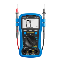
Covers CAT III 600V, 'OL' over-range display, negative polarity indicator, and low battery symbol.

LCD Display, Range Control, and Auto Functions

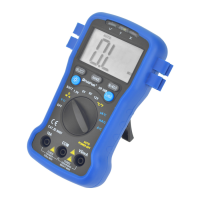
Details the 4000 counts LCD, auto range, auto power-off, and auto backlight features.

Fuse Protection, Power, and Environment Specs

Specifies fuse ratings, power supply, operating/storage temperatures, and precision conditions.

Physical Dimensions and Weight

Provides the device's physical dimensions (150x100x36mm) and approximate weight (250g).

Testing Specifications: DCV, ACV, DC Current, AC Current, Resistance, Capacitance

DC Voltage Measurement Specifications

Details DC voltage ranges, resolution, accuracy, impedance, and overload protection.

AC Voltage Measurement Specifications

Covers AC voltage ranges, resolution, accuracy, impedance, frequency response, and overload protection.

DC Current Measurement Specifications

Specifies DC current ranges, resolution, accuracy, and overload protection for fuses.

AC Current Measurement Specifications

Outlines AC current ranges, resolution, accuracy, overload protection, and frequency response.

Resistance Measurement Specifications

Provides resistance ranges, resolution, accuracy, and overload protection.

Capacitance Measurement Specifications

Details capacitance ranges, resolution, accuracy, and overload protection.

Testing Specifications: Frequency, Duty Cycle, Diode, Continuity, NCV

Frequency Measurement Specifications

Details frequency measurement ranges, resolution, accuracy, sensitivity, and overload protection.

Duty Cycle Measurement Specifications

Covers duty cycle measurement accuracy, frequency limits, sensitivity, and overload protection.

Diode and Audible Continuity Test Specs

Provides specifications for testing diodes (forward voltage) and audible continuity (resistance threshold).

Non-Contact AC Voltage Detection Specs

Details the test voltage range (90V-1000V AC) for NCV detection and indicator behavior.

Operating Instructions: Measurement Procedures

Pre-Operation Checks and Attention

Covers battery check, input jack warnings, and setting the range switch before measurement.

DC Voltage Measurement Procedure

Guides connecting leads, setting range, and taking DC voltage measurements, with usage notes.

AC Voltage Measurement Procedure

Explains how to connect leads, set range, and measure AC voltage, including important notes.

DC and AC Current Measurement Procedure

Details connecting for current measurement, selecting ranges, and series connection with load.

Resistance Measurement Procedure

Guides connecting leads, setting range, and measuring resistance, with notes on stability and in-circuit testing.

Capacitance Measurement Procedure

Explains connecting leads, setting range, and measuring capacitance, with notes on discharging and large/small values.

Frequency and Duty Cycle Measurement Procedure

Details connecting probes, selecting Hz/% key, and measuring frequency or duty cycle.

Diode and Audible Continuity Test Procedure

Guides selecting diode/continuity, connecting leads, and interpreting results, with safety notes.

Non-Contact AC Voltage Detection Procedure

Explains activating NCV detection, proper meter positioning, and indicator behavior.

Maintenance and Replacement Procedures

Battery Replacement Guide

Details the process for replacing the battery when the low battery symbol appears.

Fuse Replacement Guide

Explains how to replace the internal fuses with correct types and ratings.

General Maintenance and Cleaning

Provides instructions on test lead replacement, cleaning the meter, and general upkeep.

Accessories

Related product manuals